
 الإنجليزية
 中文简体
中文简体 Русский
 Español
 Português
 Türkçe
 العربية
 Deutsch
 Polski
 Italiano
 Français
 한국어
한국어 ไทย
ไทย Tiếng Việt
 日本語
日本語





























ارتفاع درجة الحرارة تستر
مستخدم المالكين
قابل للتطبيق LISUN الموديلات: WS-1、WS-2、WS-3
1. فتح العلبة والتعرف الأساسي على المعدات
1.1 المواصفات الفنية الرئيسية
| LISUN الموديل | WS-1 | WS-2 | WS-3 |
| محطة الاختبار | 8 | ||
| اختبار التيار | 0-50 أ | 0-200 أ | 0-300 أ |
| اختبار الجهد | أقل من 3V | ||
| عداد | قابل للتعديل من 0 إلى 9999 ثانية | ||
| ميزان الحرارة | 0–1000°C (includes 8 Type K thermocouples) | ||
| وفقا للمعيار | GB/T 2099.1، البند 19 (IEC 60884-1(البند 19) | GB/T 2099.1، البند 19 (IEC 60884-1، البند 19)، متطلبات GB 16915.1، البند 17 (IEC 60669-1، البند 17)، و GB/T 13140.1، البند 15 (IEC 60998-1، البند 15) | |
1.2 فتح العلبة والتحقق من المحتويات
1.2.1 فك التغليف والفحص البصري
عند إخراج الجهاز من العلبة، تعامل معه برفق لتجنب خدش الغلاف الخارجي بأدوات حادة. بعد إخراجه من العلبة، افحص أولاً الجزء الخارجي من الجهاز للتأكد من عدم وجود أي تشوه أو انبعاجات ظاهرة، وأن الأزرار ليست تالفة أو مفكوكة.
إذا لاحظت أي تلف أو تشوه في الجهاز أو ملحقاته، فلا تقم بتشغيل الطاقة. يرجى الاتصال بنا فوراً.
1.2.2 الوحدة الرئيسية والملحقات
جهاز قياس ارتفاع درجة الحرارة: وحدة واحدة.
The standard accessories are as follows: ① Power cord; ② Mock-up, used for testing flush-mounted electrical fixtures such as outlets; ③ Conduit; ④ 8 K-type thermocouples.
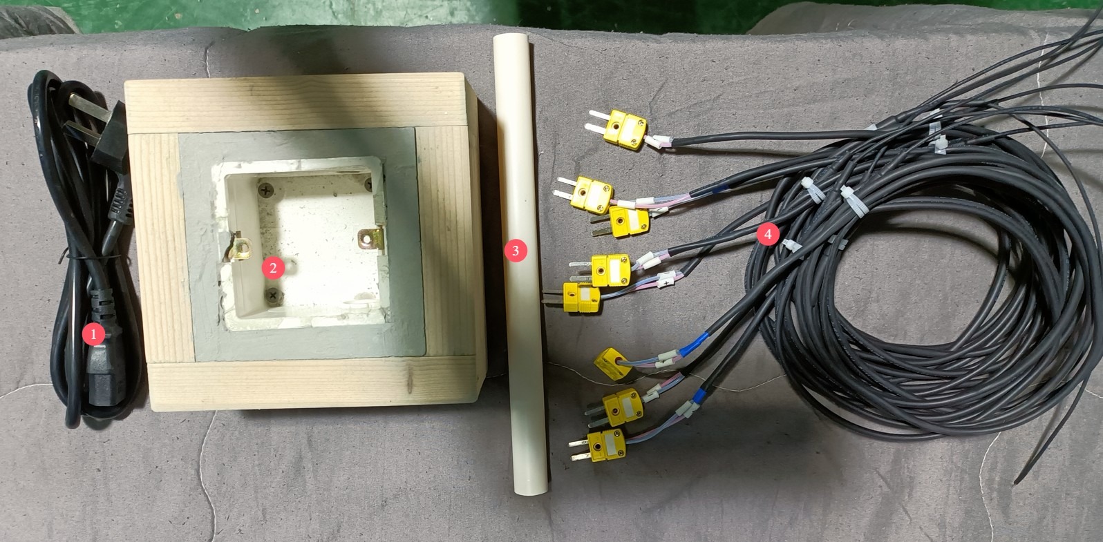
الشكل 1
Download links for the digital user manual, warranty card, and other documents have been sent to you via email. Please download them as soon as possible. If you missed the email, you can contact us to request the download links again.
1.3 وصف هيكل المعدات
1.3.1 واجهة الجهاز
① Touchscreen; ② 8-channel temperature display; ③ Test current display; ④ Power switch; ⑤ Test current adjustment.
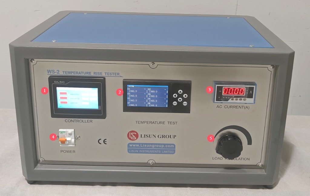
الشكل 2
1.3.2 Side and Back of the Device
① 8 Omega Type K thermocouple sockets; ② Sample terminals, capable of connecting 8 samples in series simultaneously; ③ Power cord jack.
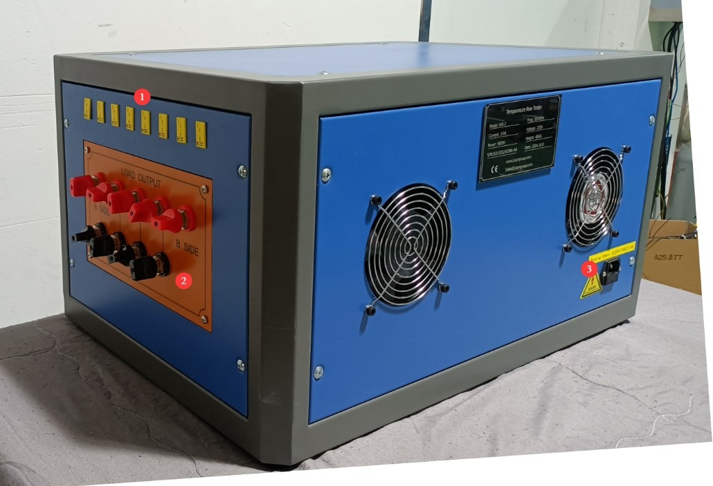
الشكل 3
2. احتياطات السلامة
2.1 السلامة الكهربائية
2.1.1 توصيل الطاقة
220V single-phase power; power outlets must comply with safety standards, have proper grounding, and have a rated current that matches the equipment’s power rating and the actual load power requirements.
2.1.2 مواصفات التأريض
The equipment must be reliably grounded, with a grounding resistance of ≤4 Ω. Do not use gas pipes, non-metallic water pipes, or neutral wires as substitutes for the grounding wire. After grounding is complete, use a Grounding Resistance Tester to measure the grounding resistance. Power may only be applied after confirming that it meets the requirements, to prevent electric shock, equipment malfunctions, or measurement errors caused by poor grounding.
2.2 سلامة التشغيل
قبل توصيل الأسلاك أو فحص المعدات أو صيانتها، يجب عليك إيقاف تشغيل مفتاح الطاقة الخاص بالمعدات ومصدر الطاقة الرئيسي، والتأكد من عدم وجود جهد متبقٍ قبل المتابعة؛
تجنب تشغيل مفتاح الطاقة أو شاشة اللمس أو أزرار الجهاز بأيدٍ مبللة لتجنب خطر الصدمة الكهربائية؛
لا تضع أي أجسام غريبة (مثل الأدوات أو الورق) داخل خزانة التحكم الكهربائية لمنع الغبار أو الأجسام الغريبة من التسبب في حدوث دوائر قصر أو إتلاف المكونات؛
لا تقم بتوصيل أو فصل أسلاك الطاقة أو كابلات الإشارة أثناء تشغيل الجهاز لمنع حدوث دوائر قصر قد تتلف وحدة التحكم أو المكونات الكهربائية؛
الجهاز قادر على إخراج تيارات عالية. عند توصيل الأسلاك أو استبدال العينات أو ضبط الدوائر، يجب عليك أولاً إيقاف تشغيل الطاقة وضبط مقبض التحكم في تيار الحمل على أدنى إعداد لضمان عدم وجود خرج حمل ولمنع حدوث صدمة كهربائية؛
لا تلمس العينة أو أطراف المزدوجة الحرارية أو موصلات خرج الحمل أثناء الاختبار لتجنب الحروق الناتجة عن درجات الحرارة العالية أو الصدمات الكهربائية؛
Warning signs must be posted in the test area to prohibit unauthorized personnel from approaching, in order to prevent accidental contact with high-temperature samples or live electrical components.
2.3 السلامة البيئية
يجب وضع المعدات في بيئة داخلية مستوية وجافة وجيدة التهوية، بعيدًا عن المواد القابلة للاشتعال والانفجار والغازات المسببة للتآكل والمجالات المغناطيسية القوية.
يجب تركيب المعدات في غرفة مكيفة، مع الحفاظ على درجة الحرارة المحيطة بين 5 درجات مئوية و 35 درجة مئوية والرطوبة النسبية ≤ 85٪.
The distance between the equipment and walls, as well as surrounding structures (such as other test equipment and shelving), must be at least 1000 mm to facilitate operation and maintenance; at least 2000 mm of space must be left in front of the equipment to ensure smooth operation and keep the surrounding area free of obstructions;
2.4 أخرى
بالنسبة للأمور غير المشمولة في هذا الدليل، يرجى توخي الحذر أو الاتصال بنا.
3. مقدمة لبرنامج الشاشة اللمسية
3.1 واجهة الاختبار
① Start timer; ② Start test power supply; ③ Reset; ④ Display of sample power-on duration; ⑤ Display of sample power-off duration; ⑥ Display of number of repetitions.
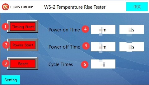
الشكل 4
3.2 صفحة إعدادات المعلمات
① Setting the duration of power application to the sample; ② Setting the duration of power disconnection from the sample; ③ Setting the number of repetitions; ④ Setting the duration of the alarm.
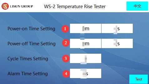
الشكل 5
4. الاستعدادات قبل الاختبار
4.1 تهيئة البيئة
وفقًا للمتطلبات القياسية، يجب وضع مجموعة الاختبار في بيئة خالية من التيارات الهوائية أثناء الاختبار لمنع تدفق الهواء من التأثير على دقة قياسات درجة الحرارة.
When testing flush-mounted electrical accessories, a test environment that complies with the standards must be set up in advance (see the model in the “General Accessories” section): Place the mounting box into the pine trough and fill the space between the mounting box and the trough with plaster, ensuring that the front edge of the mounting box is flush with the front surface of the pine trough (with a deviation of no more than ±5 mm). The plaster should be 10 mm to 15 mm thick, and the pine trough must have at least 25 mm of wood surrounding the plaster; After the test assembly is constructed, it must be allowed to dry for at least 7 days.
Note: If you need models in other sizes, please contact us or manufacture them yourself according to the specifications.
4.2 Confirmation of Standards Used
4.2.1 تحديد معايير الاختبار
بحسب نوع العينة التي يتم اختبارها، يُرجى الرجوع إلى المعيار ذي الصلة لتحديد المعايير الرئيسية:
| نوع العينة | المعايير المرجعية | اختبار التيار | مدة الاختبار | حد ارتفاع درجة الحرارة |
| المقابس/المنافذ | غب / T شنومكس-شنومكس | كما هو محدد في الجدول 20 (على سبيل المثال، بالنسبة للمقابس متعددة المنافذ، استخدم التيار المقنن المقابل) | 60 ± 5 دقائق | أطراف التوصيل، والموصلات، ومكونات التثبيت ≤ 45 ألف |
| مفاتيح | GB 16915.1-2024 | As specified in Table 17 (e.g., 20 A test current for a 16A circuit breaker) | 1h | أطراف التوصيل ≤ 45 كيلو أوم؛ مقابض/أيدي غير معدنية ≤ 5 كيلو أوم؛ مكونات خارجية أخرى غير معدنية ≤ 55 كيلو أوم؛ مقابض/أيدي معدنية ≤ 35 كيلو أوم؛ مكونات خارجية أخرى معدنية ≤ 45 كيلو أوم |
| الموصلات | غب / T شنومكس-شنومكس | كما هو محدد في الجدول 2 (على سبيل المثال، تيار اختبار 24 أمبير لسعة توصيل 2.5 مم²) | الوصول إلى التوازن الحراري (ارتفاع درجة الحرارة ≤ 1 كلفن خلال ساعة واحدة) | المكونات الحاملة للتيار في الجزء المثبت ≤ 45 كيلو أوم |
| Note: For switches with indicator lights, if the circuit current is ≤3 mA (neon lamp/LED), temperature rise tests related to the indicator light may be omitted; when testing protective devices (such as fuses), use low-impedance wire to short-circuit the circuit. | ||||
4.2.2 التحقق من صحة وضع الاختبار
حدد ما إذا كان اختبار دورة التحميل/عدم التحميل مطلوبًا (راجع متطلبات المعيار ذات الصلة)؛ إذا كان اختبار الدورة مطلوبًا، فحدد عدد الدورات، ومدة كل فترة تشغيل، ومدة كل فترة إيقاف تشغيل؛
Verify the temperature measurement method (this device uses a thermocouple for measurement) and ensure that the thermocouple is positioned so as not to affect measurement accuracy (e.g., near critical areas such as clamping components or terminals).
4.3 تحضير العينة
4.3.1 اختيار العينة وإعدادها
Select representative samples (such as plugs, receptacles, switches, terminal blocks, etc.) based on the test requirements, ensuring that the samples are in good condition, free of damage, and consistent with the product’s condition upon shipment;
Electrical accessories with detachable wiring must be connected to polyvinyl chloride (PVC)-insulated wires with the corresponding rated cross-sectional area as required by the standard (see the table below); accessories with non-detachable wiring shall be tested as delivered;
المساحة المقطعية الاسمية للموصلات النحاسية المستخدمة في اختبارات ارتفاع درجة الحرارة (راجع GB/T 2099.1-2021):
| التصنيف الحالي (a) | ملحقات كهربائية ثابتة | ملحقات كهربائية محمولة |
| ≤ 10 | سلك صلب/مجدول 1 مم² | سلك مرن، 1.5 مم² |
| >10 و ≤16 | سلك صلب/مجدول 1.5 مم² | سلك مرن، 2.5 مم² |
| > 16 | سلك صلب/مجدول، 4 مم² | سلك مرن، 6 مم² |
يجب شد براغي أو صواميل الطرفية إلى 2/3 من عزم الدوران المحدد (انظر المتطلب 12.2.8 من المعيار GB/T 2099.1-2021).
4.3.2 نموذج التركيب
مخرج مثبت داخل الجدار: يتم تركيبه في صندوق مثبت داخل الجدار، والذي يوضع في تجويف من خشب الصنوبر ويُملأ بالجص حسب الحاجة. يدخل الكابل من أعلى الصندوق، ويتم إغلاق نقطة الدخول لمنع دوران الهواء. يبلغ طول كل موصل داخل الصندوق (80±10) مم؛
Surface-mount outlets/switches: Mounted at the center of a pine block, which must be at least 20 mm (thick) × 500 mm (wide) × 500 mm (high);
Plug: Place it in the center of a pine block (block specifications as above); if the plug has a side grounding prong or a spring-loaded grounding prong, it must be inserted into a standard fixed outlet for testing;
منافذ ثابتة متعددة (أطراف مشتركة): أدخل قابس الاختبار في ظل الظروف الأكثر سوءًا لضمان أن توزيع تيار الاختبار يفي بالمتطلبات؛
الموصلات: تُستخدم أطراف التوصيل أحادية القطب لتوصيل الأسلاك وفقًا لطريقة محددة مسبقًا، بينما تُستخدم أطراف التوصيل متعددة الأقطاب لتوصيل ما يصل إلى ثلاثة أطراف متجاورة. يجب أن تتوافق أطوال الأسلاك مع المتطلبات القياسية (متر واحد للأسلاك التي تقل مساحتها عن أو تساوي 10 مم²، ومتران للأسلاك التي تزيد مساحتها عن 10 مم²؛ ويمكن تقصير الأطوال وفقًا لمواصفات الشركة المصنعة).
4.4 تجهيز المعدات
4.4.1 نموذج اتصال
Connect the components in series in the direction indicated by the black lines in the figure below. When the load current is high, use sufficiently thick connecting wires to ensure that the wires’ current-carrying capacity matches the test current and to prevent the wires from overheating.
If connecting only one sample, connect terminals ① and ⑨; if connecting two samples in series, connect the first sample to terminals ① and ②, and the second sample to terminals ② and ⑨; If you need to connect three samples in series, connect the first sample to terminals ① and ②, the second sample to terminals ② and ③, and the third sample to terminals ③ and ⑨. And so on.
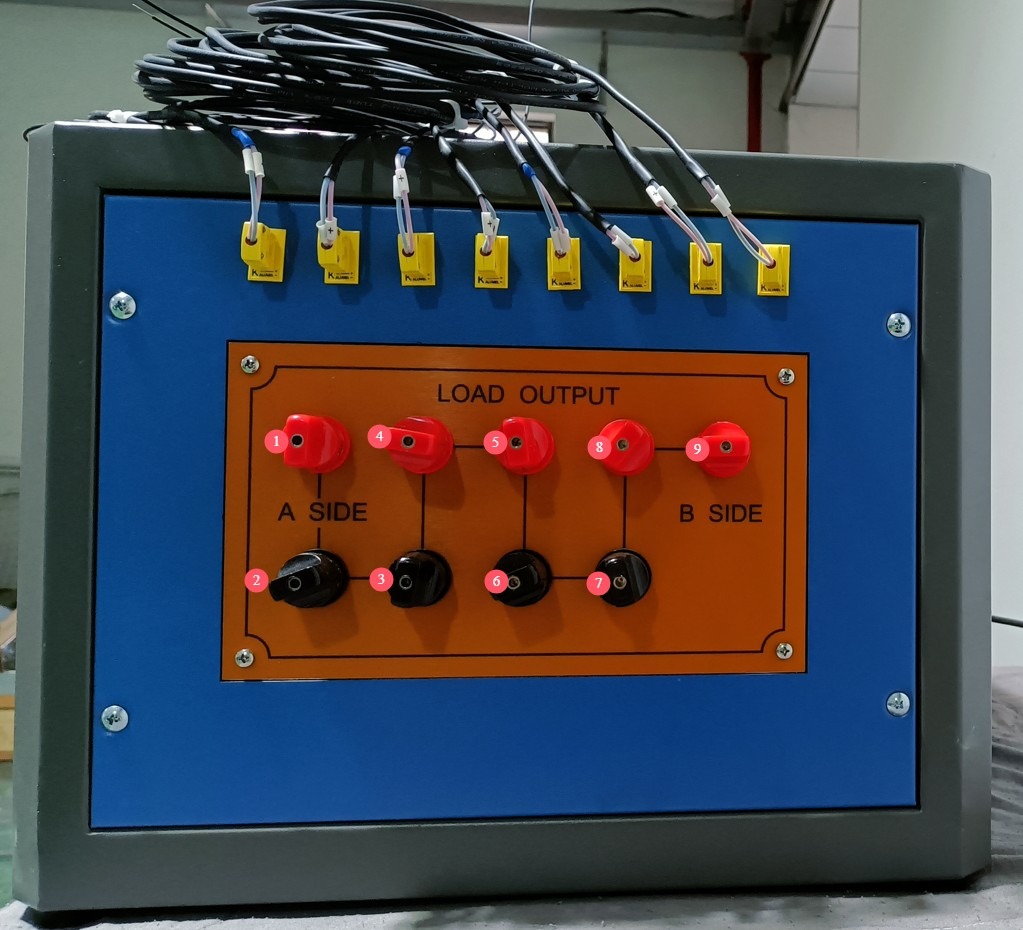
الشكل 6
لنأخذ مثالاً على ذلك مقبس كهربائي مُثبّت داخل الجدار، فبعد توصيل جميع الأسلاك، سيبدو كما في الصورة أدناه. ستحتاج إلى توصيل طرفي المقبس ببعضهما لتوليد تيار اختبار للدائرة.
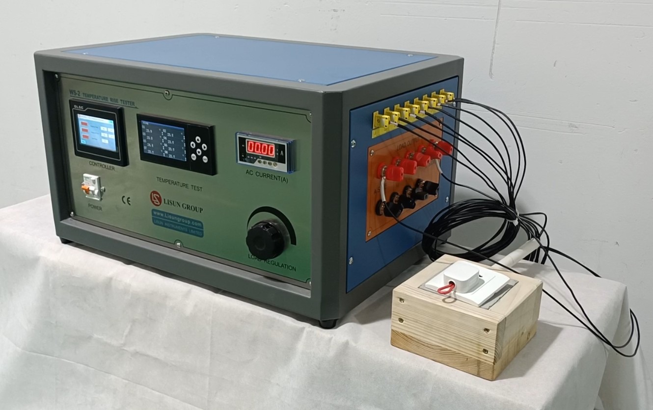
الشكل 7
ملاحظة: يجب أن يتوافق تركيب النموذج والأسلاك مع المتطلبات القياسية لمنع وصلات الأسلاك غير المحكمة التي قد تسبب ضعف الاتصال أو حدوث شرارة كهربائية.
Select the key points where temperature measurements are required (such as terminals, connectors, clamping components, and housings). Securely attach the other end of the thermocouple (the sensing end) to the measurement point using high-temperature-resistant tape or adhesive (such as Loctite 7452), ensuring tight contact with the sample surface and that it does not come loose.
4.4.2 تهيئة المعدات
To ensure safety, first turn the front-panel test current adjustment knob counterclockwise to the lowest setting. Then turn on the device’s power switch and let it warm up for 15 minutes. Proceed with the next steps only after the touchscreen display has stabilized and the temperature display shows no abnormal fluctuations.
5. Operating Procedures for the Temperature Rise Test
5.1 إعدادات المعلمات
Access the touchscreen parameter settings interface and set the following: ① sample power-on time, ② sample power-off time, ③ number of cycles, and ④ alarm duration (the device will sound an alarm when the test is complete). Note: Please refer to the relevant standard requirements to determine whether the test requires a power-on/power-off cycle and how long the test should last. After completing the settings, click “Test” to return to the test interface.
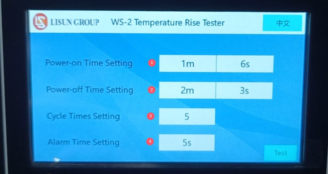
الشكل 8
5.2 Commissioning: Current Testing and Startup Testing
① Tap “Test Power-On” on the touchscreen, ② turn the load current adjustment knob, and ③ adjust the real-time current displayed here to meet the test requirements (please refer to the applicable standard to determine the specific current required).
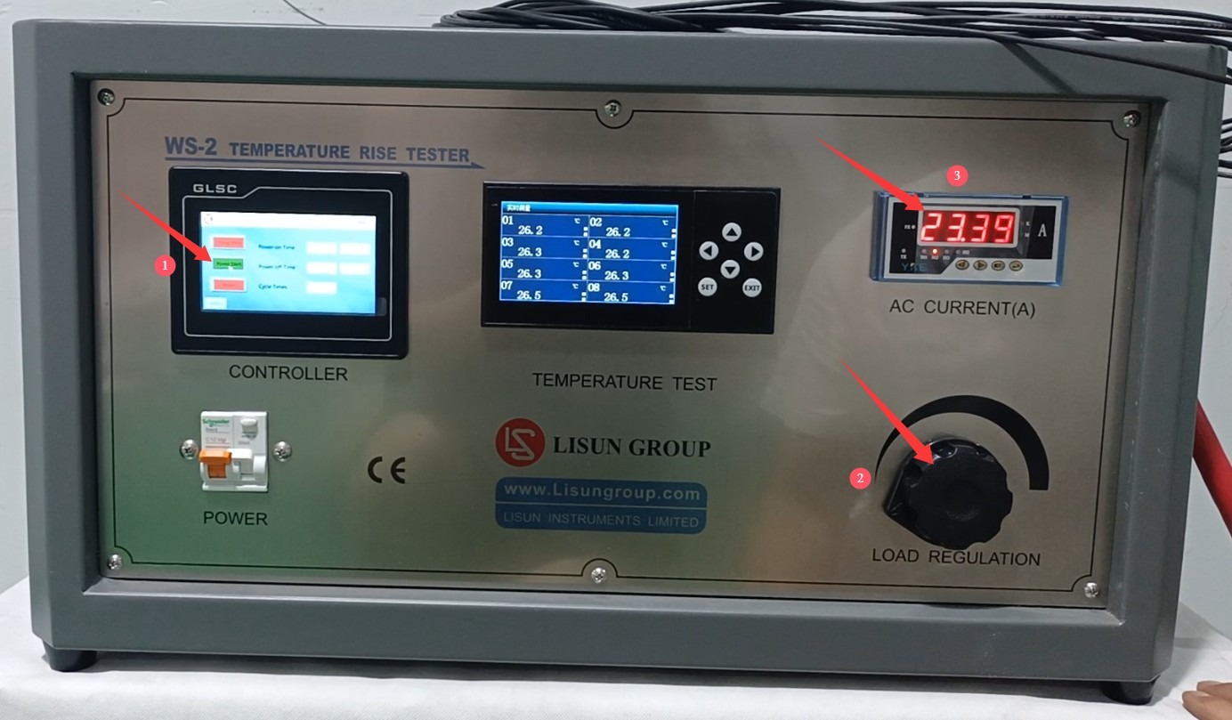
الشكل 9
Note: Adjust the current gradually to avoid sudden spikes or drops that could damage the equipment or the sample.
Once the test current has stabilized (fluctuation range ≤ ±0.5%), click “Start Timer” to begin the test. During the test, monitor the displayed temperature to determine whether the sample has passed the test.
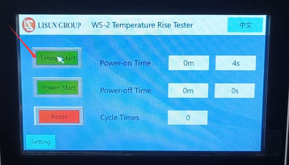
الشكل 10
Temperature data must be closely monitored during the test. If an abnormal spike in temperature or an alarm occurs, the test should be stopped immediately to investigate any issues with the sample or equipment.
5.3 مراقبة عملية الاختبار
Monitor the temperature data on the display in real time, and record the initial temperature (when the power is off) and temperature changes during the test;
Monitor the load current display to ensure that the current remains stable within the test current range at all times. If abnormal fluctuations in the current occur, promptly investigate the cause (such as loose connections or poor contact with the sample);
If there is an abnormal spike in temperature or an alarm is triggered, the test should be stopped immediately to investigate any issues with the sample or equipment.
During the test, do not alter parameters, touch the wiring, or move the sample without authorization to ensure stable test conditions.
6. إجراءات ما بعد الاختبار
6.1 Equipment Operation
6.1.1 إنهاء الاختبار
After the test is complete, wait for the device to automatically cut off the test current, or manually click “Start Test Power” again to cut off the test current;
انقر على زر "إعادة الضبط" الموجود على الشاشة اللمسية لمسح البيانات من هذا الاختبار وإعادة الجهاز إلى حالته الأولية؛
Slowly turn the test current adjustment knob counterclockwise to the lowest position, then turn off the device’s power switch.
6.2 معالجة البيانات
6.2.1 تسجيل البيانات
سجل بيانات درجة الحرارة قبل الاختبار وبعده (درجة الحرارة الأولية، ودرجة الحرارة النهائية، وأقصى ارتفاع في درجة الحرارة)، واحسب ارتفاع درجة الحرارة باستخدام الصيغة التالية: ارتفاع درجة الحرارة (كلفن) = درجة الحرارة النهائية (°م) - درجة الحرارة الأولية (°م)؛
Record the test current, test duration, number of cycles (if applicable), sample model, serial number, and test environment parameters (temperature, humidity), and compile this information into a test record form.
6.2.2 تفسير النتائج
Comparison of Temperature Rise Data from Comparative Tests with Standard Limits:
① If the temperature rise is ≤ the standard limit, the sample is deemed to meet the temperature rise requirement;
② If the temperature rise exceeds the standard limit, the sample is deemed nonconforming, and the cause of the nonconformity must be analyzed (e.g., the connector sleeve is too thin, poor contact, insufficient wire cross-sectional area, etc.).
6.3 Sample and Equipment Preparation
6.3.1 إزالة العينة
After the sample has cooled to room temperature, remove the load wires and thermocouples one by one. When removing them, avoid pulling on the wires with force to prevent damage to the sample or the thermocouples;
افحص حالة العينة بعد الاختبار (على سبيل المثال، ما إذا كانت مشوهة أو محروقة أو بها وصلات مفكوكة) وسجل التفاصيل ذات الصلة.
6.3.2 تنظيم المعدات
قم بتنظيم الملحقات مثل المزدوجات الحرارية وأسلاك التوصيل، وقم بتخزينها بشكل أنيق لمنع تشابك الأسلاك أو تلفها؛
Clean the surface of the equipment (wipe with a dry cloth; do not get it wet), remove any debris from the test area, and keep the environment tidy.
7. الصيانة والعناية اليومية
7.1 متطلبات التخزين قصير الأجل
إذا تم استخدام المعدات بشكل يومي، فلا يلزم اتخاذ أي إجراء إضافي بعد اكتمال التنظيف عقب كل اختبار.
7.2 متطلبات التخزين طويل الأجل
إذا لم يتم استخدام الجهاز لفترة طويلة (أكثر من شهر واحد)، فيرجى فصل جميع الكابلات وتغطية الجهاز بغطاء واقٍ من الغبار لمنع تراكم الغبار.
ينبغي تشغيل الجهاز مرة واحدة شهريًا لمدة نصف ساعة فقط لمنع تلف المكونات الكهربائية (مثل المكثفات والموصلات).
8. استكشاف الأخطاء وإصلاحها وحل المشكلات الشائعة
8.1 الجهاز لا يعمل
8.1.1 أسباب الفشل
سلك الطاقة غير موصول بشكل صحيح أو تالف؛ لا يوجد طاقة أو أن الجهد غير طبيعي؛ انصهر فيوز الجهاز؛ مفتاح الطاقة معطل.
8.1.2 طرق العلاج
Check that the power cord is securely connected, the plug is firmly inserted, and the power cord is not damaged; if damaged, replace it. Use a multimeter to verify that the supply voltage is AC 220 V ± 10%; if there is no power, troubleshoot the power circuit; Check whether the fuse has blown; if so, replace it with a fuse of the same specification (never substitute with other conductors). If none of the above issues are found, the power switch may be faulty; contact the manufacturer for repair.
8.2 The current cannot be adjusted or is unstable
8.2.1 أسباب الفشل
مقبض ضبط تيار الحمل تالف؛ وصلة سلك العينة مفكوكة أو بها اتصال ضعيف؛ محول الجهد معيب؛ العينة موصلة بشكل غير صحيح أو العينة نفسها معيبة (على سبيل المثال، دائرة مفتوحة).
8.2.2 طرق العلاج
Check whether the knob rotates smoothly without any sticking; if damaged, replace it. Re-inspect the sample wiring, tighten any loose connections, check for short circuits, and replace any damaged sample wires; Disconnect the sample wiring and directly short-circuit the device’s sample terminals. If the current still cannot be adjusted or remains unstable, the Voltage Transformer may be faulty; contact the manufacturer for repair. Check whether the sample wiring meets the requirements and whether the sample is functioning properly (e.g., no open circuits). Replace any faulty samples and try again.
8.3 Inaccurate temperature measurement or no display
8.3.1 أسباب الفشل
The thermocouple is not connected properly or is damaged; there is poor contact between the thermocouple and the sample surface; the temperature measurement module is malfunctioning; the display shows an error.
8.3.2 طرق العلاج
Check whether the thermocouple is securely connected to the device interface; try unplugging and replugging it. If the thermocouple is broken or the insulation is damaged, replace it; Check whether the thermocouple’s sensing tip is in close contact with the sample; reattach it securely to ensure it is not loose; compare the measurement with a standard thermometer. If the deviation is too large, the temperature measurement module may be faulty; contact a calibration or repair service. If a single temperature channel shows no display, the interface for that channel may be faulty; try testing by switching to a different thermocouple interface.
8.4 Equipment Alarm Anomalies
8.4.1 أسباب الأعطال
ارتفاع درجة الحرارة يتجاوز الحد المحدد مسبقاً؛ انقضى وقت الاختبار؛ تيار غير طبيعي (حمل زائد).
8.4.2 طرق العلاج
If a temperature rise exceeds the limit and triggers an alarm: Immediately stop the test, check whether the sample is in good condition, whether the thermocouple is positioned correctly, and whether the test parameters comply with the standard; after troubleshooting, repeat the test. If a time-out alarm is triggered: This is a normal occurrence; proceed according to the test completion procedure. If an abnormal current alarm is triggered: Check whether the current setting exceeds the rated value; after troubleshooting, reset the equipment;