
 الإنجليزية
 中文简体
中文简体 Русский
 Español
 Português
 Türkçe
 العربية
 Deutsch
 Polski
 Italiano
 Français
 한국어
한국어 ไทย
ไทย Tiếng Việt
 日本語
日本語





























دفعة اختبار مولد
مستخدم المالكين
قابل للتطبيق LISUN الموديلات: SUG-CCITT-A、SUG-CCITT-C
We guarantee that the product is in good working order upon unboxing. If a serious quality issue is discovered within one week of purchase (as evidenced by the invoice date), we will provide a free replacement upon confirmation by our technical department or an authorized dealer.
Please keep your warranty card in a safe place and present it when contacting us for warranty or repair services. A free warranty is provided for one year from the date of manufacture (excluding wear-and-tear parts). After one year, paid services will apply, and you will receive a discount on applicable charges upon presentation of the card.
1. Function and Principle
The pulse waveforms of the SUG-CCITT-A Lightning Surge Test System comply with the IEC 61000-4-5 standard issued by the International Electrotechnical Commission and the Chinese national standard GB/T 17626.5. It is a testing instrument used to evaluate the surge immunity of electrical and electronic products, such as industrial process measurement and control devices. It establishes a common basis for evaluating the reliability of equipment under test when input/output (I/O) lines or communication lines are subjected to high-energy interference.
There are two main causes of lightning strikes:
1. Switching Transients
Switching transients are related to the following factors:
Switching disturbances in the main power supply system, such as the switching of capacitor banks.
The startup or shutdown of other equipment near the test equipment, as well as changes in the load within the power distribution system.
Switch thyristor devices connected to resonant circuits.
Faults in various systems, such as short circuits and arcing faults in equipment grounding networks or grounding systems.
2. Lightning Transients
The main mechanisms behind lightning transients:
When lightning strikes an external (outdoor) line directly, it injects a large current, and as the current flows through the grounding resistance or the surge impedance of the external line, it generates a voltage.
Indirect lightning strikes (those occurring between or within clouds) may induce voltages in electrical conductors on the exterior or interior of a building.
When a lightning strike hits an object near a power line rather than the line itself, it can create an electromagnetic field that induces a voltage in the conductors of the external power line.
Interference caused by lightning ground currents generated by a direct discharge to the ground near the equipment, which are coupled into the equipment’s common grounding system.
In addition, rapid changes in current and voltage generated when the protectors of certain devices are triggered may also be coupled into the devices themselves.
2. نظرة عامة على الجهاز
1. Instrument Hardware
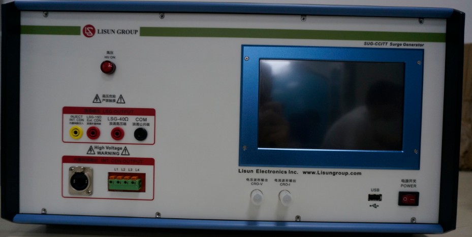
This device has a built-in CDN; the specifications are as follows:
Built-in Network Capacity DC 50 V, 0.1 A
Built-in Network Coupling Method Wire-to-Ground(T1+R1+T2+R2 simultaneously connected to GND)
Built-in network coupling components: 100 Ω per line + 90 V gas-discharge tube
معدل نقل البيانات: 100 ميغابت / ثانية
Operating voltage: Maximum 50 V DC
Operating current: Maximum 1 A
2. Parts Box:
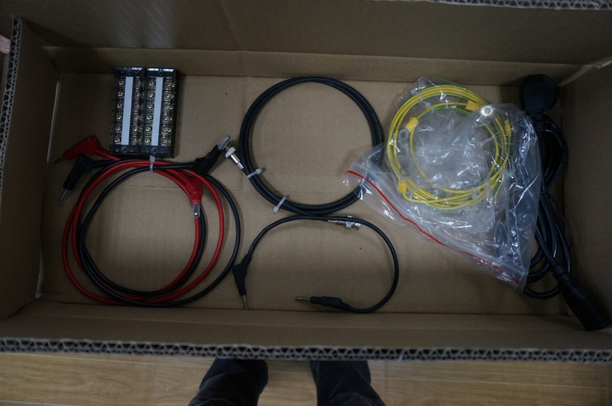
3. Packaging Overview
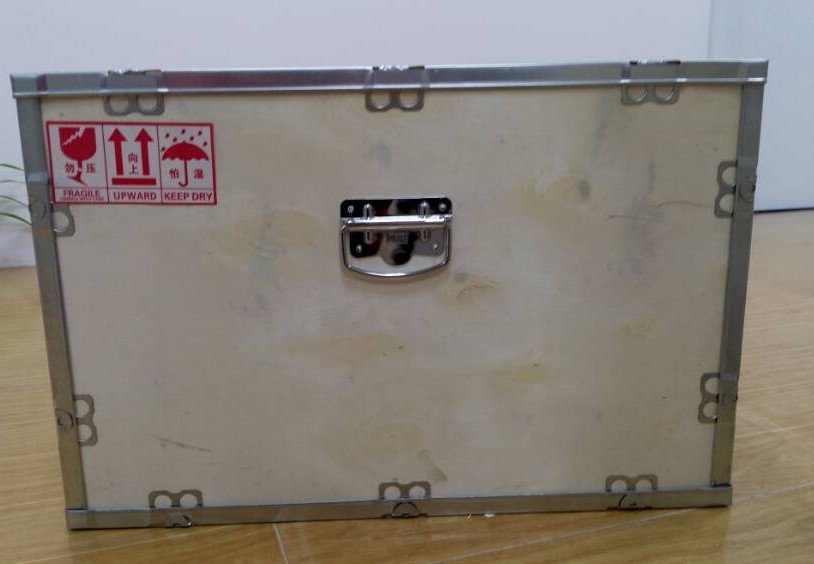
Outer packaging: Packaged in a wooden crate with metal handles on the outside.
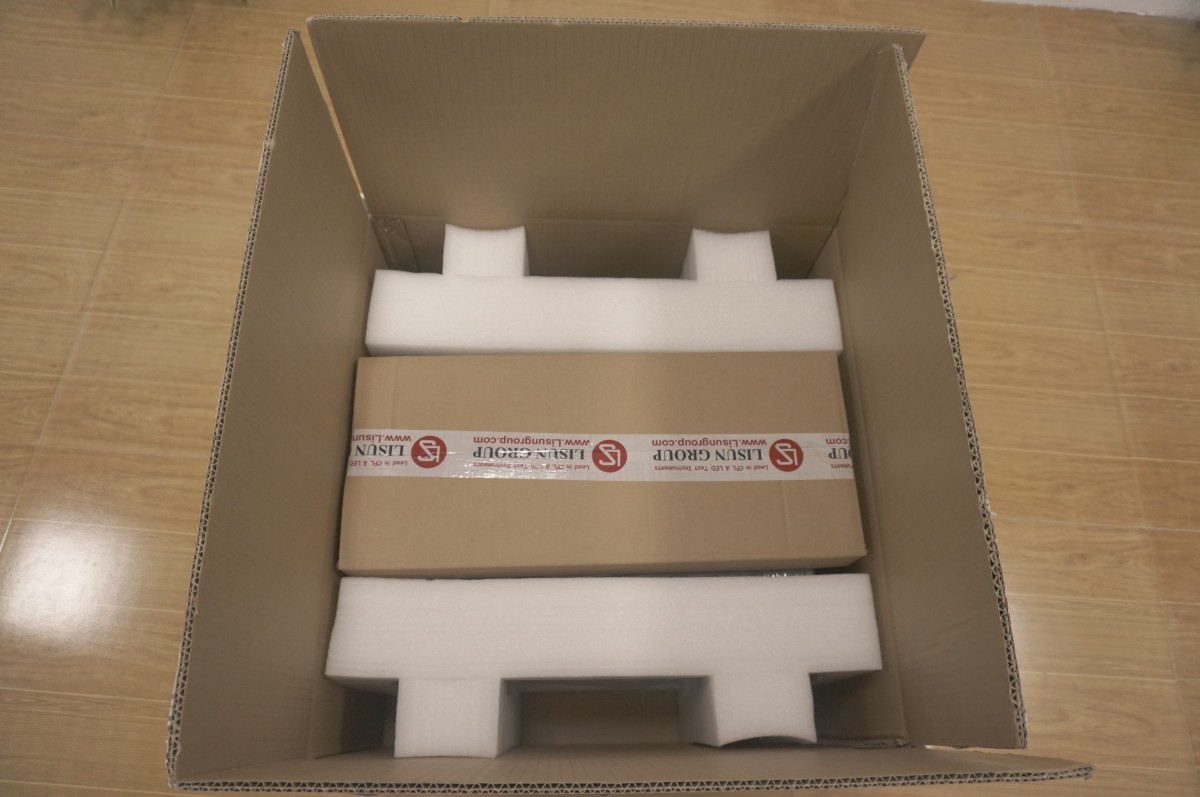
Inner Packaging: Packaged in a cardboard box with foam padding inside.
The main unit of the instrument is packaged in plastic.
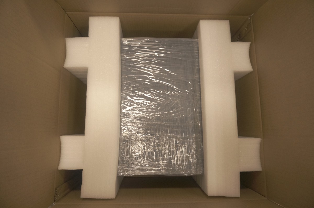
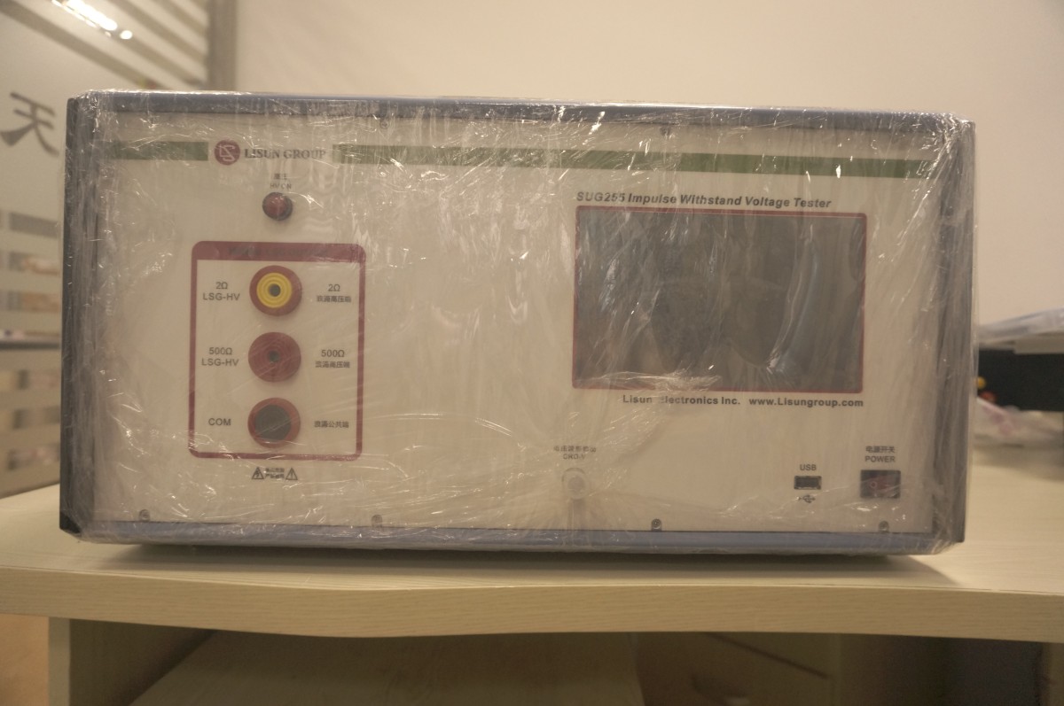
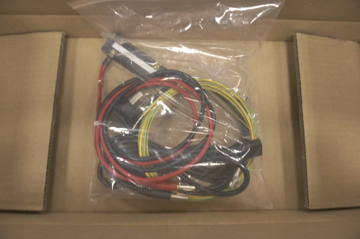
Accessory packaging: Paper box.

The accessories are packed in plastic bags.
3. Instrument Installation and Operation
Introduction to the Equipment Front Panel
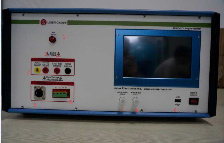
High-Voltage Warning Light: When this light is on, it indicates that the instrument is outputting high voltage. Danger!
Built-in network injection port.
15-ohm output terminal
40Ω output terminal
Communication Line Output Terminal
8-line high-speed network output (backup/optional feature)
Voltage Waveform Interface
Current Waveform Interface
USB port: Used to update the device’s software or to operate it with a mouse.
Introduction to the Rear Panel of the Device
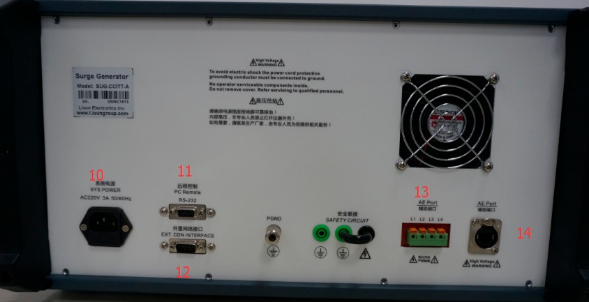
Device Power Connector
Remote Control Unit (Spare)
External Network Interfaces (Active/Standby)
Communication Line Test Auxiliary Interface
8-Line High-Speed Network Test Auxiliary Interface
توصيلات المعدات
For wiring, please refer to the labels in the figure above:
During normal testing, use the short jumper wire provided with the device to short-circuit pins “2” and “3.” Connect the test communication cable to pin “5” (or “6”), ensure the device is properly grounded, and you are ready to begin testing.
When conducting auxiliary network testing, in addition to the steps described in the first step, connect the test lead to port “13” (or “14”) on the rear panel of the instrument, and turn on the device under test so that it is in normal operating condition. You can then begin the test as usual.
4. Instrument Operation
شاشة بدء التشغيل
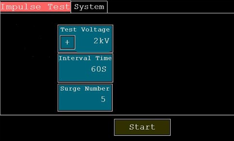
The image above shows the initial screen after startup. The top row is the function selection menu; simply tap the corresponding area to access the corresponding function screen.
Click to enter the voltage setting interface; users can enter a test voltage between 0.1 and 10 kV as needed.
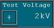
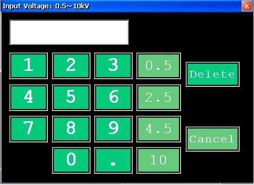
Click to toggle the surge polarity (“+” indicates positive polarity, “-” indicates negative polarity); once you’ve finished setting it, click to confirm the voltage setting.

Click to enter the discharge interval settings screen. Users can set the discharge interval according to their needs, with a discharge time ranging from 1S to 99S. After completing the settings, click “Confirm” to save the interval settings.
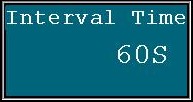
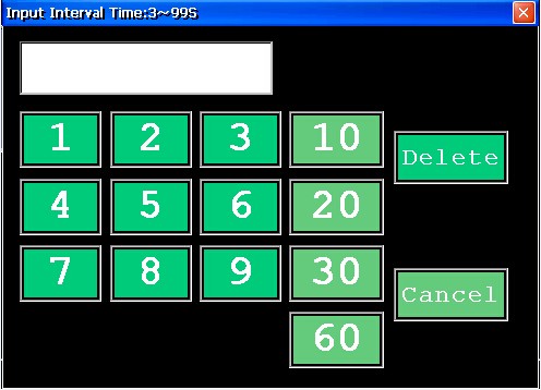
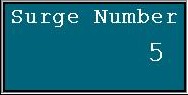
Click to enter the discharge count settings screen. Users can set the discharge count according to their needs; the range is 1–999. After setting the count, click “Confirm” to save the discharge count settings.
Once all parameters have been set, click to start the test. A “beep” will sound during the last 5 seconds of the countdown. When the test ends, ten rapid “beeps” will sound as a reminder. After the test is complete, turn off the power.
Note: High voltage remains stored in the instrument immediately after the test ends; it will dissipate after 15 seconds.
4. ملاحظات مهمة
The Impulse Test Generator generates high-energy surges (high voltage, high current) during operation. For safety reasons, please read this manual and use the device correctly. Please observe the following precautions during use:
Do not use this device when your hands are wet or when the relative humidity exceeds 75%.
Please ensure that the grounding prong of the power outlet is properly grounded.
Because a high-voltage pulse is applied to the terminal block (Surge out), if you need to change the wiring, you must first verify that the high-voltage power supply is turned off (the HV. POW light is off) before proceeding.
Operations must strictly follow the instructions in the user manual.
Although electric shock is rare when operating this device, for safety reasons, do not eat while operating it to prevent accidental choking caused by an electric shock.
This equipment uses vacuum contactors to generate voltage pulses. To ensure the service life of the vacuum switches, do not apply high voltage when the equipment is not in use, and especially do not continuously trigger the vacuum contactors under high voltage.
This device contains high voltage. Do not disassemble or work with the casing open. Non-professionals are prohibited from opening the instrument casing.
5. قائمة التعبئة
| 1 | مضيف | 1 |
| 2 | 220V Single-Phase Power Cord | 1 |
| 3 | سلك ارضي | 1 |
| 4 | Oscilloscope Cables | 1 |
| 5 | Test Object Connecting Cable | 1 |
| 6 | دليل المستخدم | 1 |
| 7 | شهادة المطابقة | 1 |
| 8 | بطاقة الائتمان | 1 |