
 الإنجليزية
 中文简体
中文简体 Русский
 Español
 Português
 Türkçe
 العربية
 Deutsch
 Polski
 Italiano
 Français
 한국어
한국어 ไทย
ไทย Tiếng Việt
 日本語
日本語





























متر مكثف
مستخدم المالكين
قابل للتطبيق LISUN الموديلات: LS6515EN،LS6515FN،LS6517N
Instrument Grounding This instrument is a Class I safety instrument. When connecting it to a power source, make sure the power outlet has a Grounding wire. If Grounding, there is a risk of static or induced electricity on the instrument’s housing, which could result in personal injury!

Electric Shock Hazard Take precautions against electric shock when operating, testing, or performing maintenance on this instrument. Non-professionals must not open the unit’s enclosure without authorization. If a professional needs to replace a fuse or perform other maintenance, be sure to unplug the power cord first and perform the work only when accompanied by another person.
Even after the power cord has been unplugged, the charge stored in the capacitor may still pose a hazard; therefore, do not handle the device until it has been discharged.
The high-voltage output terminals on the instrument’s front panel carry high voltage. Never touch them with your hands to avoid electric shock.
Do not replace or adjust the instrument’s internal circuitry or components without authorization.
Electrical Shock Hazard Removing or connecting the device under test incorrectly during the testing process may result in serious injury or property damage due to high voltage at the test terminals!!! Never touch the test terminals directly with your hands.
Input power supply Please use an input power supply that meets the specifications for this instrument. Using an input power supply that does not meet these specifications may damage the instrument.

عند استبدال الفيوز، تأكد من استخدام فيوز بنفس المواصفات.
ابتعد عن الغازات المتفجرة
Electronic instruments must not be used in environments containing flammable or explosive gases, or in environments containing corrosive gases or dust, to avoid creating a hazard.
Other Safety Precautions Do not apply any voltage or current sources to the test terminals of this instrument. When testing with an external bias current or voltage source, isolation measures must be in place.

You must strictly observe all safety precautions during any operation or maintenance of this instrument. Failure to observe these safety precautions and the warnings in this manual may not only affect the instrument’s performance but may also result in direct damage to the instrument and pose a risk to personal safety. LISUN assumes no responsibility or liability for any consequences resulting from failure to comply with these safety precautions,
1. فحص الأجهزة وإعدادها
Thank you for purchasing and using our company’s products! This chapter primarily covers the checks you should perform upon receiving the instrument, as well as the requirements you must understand and meet before using it safely.
1.1 Pre-shipment Inspection
After unpacking the unit, you should first check for any external damage that may have occurred during shipping. Do not turn on the power switch without first checking the unit, as doing so may result in an electric shock.
Please verify the contents of the shipment against the packing list. If there are any discrepancies, please contact our company or distributor as soon as possible to protect your rights.
1.2 فحص مصدر الطاقة
The power supply provided to the instrument must meet the following conditions:
Voltage: 100–120 VAC or 198–242 VAC, depending on the power settings on the rear panel.
Frequency: 46 to 64 Hz.
Power: Must be greater than 85 VA.
The input power supply phase line (L), neutral line (N), and ground line (E) must match the configuration of this instrument’s power plug.
It should be used in a low-noise environment whenever possible.
Warning: To prevent electric shock that could damage the instrument or injure people, users must ensure that the ground wire of the power supply Grounding securely grounded.
1.3 المتطلبات البيئية
Do not use this product in environments with excessive dust, vibration, direct sunlight, or corrosive gases.
The instrument should be operated at temperatures between 0°C and 40°C and relative humidity of ≤75%. Therefore, please use the instrument under these conditions whenever possible to ensure measurement accuracy.
The rear panel of this test instrument is equipped with a cooling system to prevent internal temperature from rising. To ensure proper ventilation and maintain the instrument’s accuracy, do not block the left and right ventilation openings.
This instrument has been carefully designed to minimize interference from noise in the AC input power supply; however, it should still be used in a low-noise environment whenever possible. If this is unavoidable, please install a power filter.
If the instrument will not be used for an extended period, please place it in its original packaging or a similar box and store it in a well-ventilated room at a temperature between 5°C and 40°C and a relative humidity of no more than 85% RH. The air should be free of harmful impurities that could corrode the instrument, and direct sunlight should be avoided.
Instruments—especially the test leads connected to the device under test—should be kept away from strong electromagnetic fields to prevent interference with the measurements.
1.4 Fuse Requirements
The instrument is shipped with a fuse already installed; users should use the fuse provided by the manufacturer.
If you need a fuse, please contact your nearest LISUN sales office. To inspect or replace the fuse, unplug the power cord and remove the fuse holder.
Warning: Before turning on the power, make sure the fuse setting matches the supply voltage range.
1.5 Instrument Accuracy Guarantee
To ensure accurate measurements, the instrument should be allowed to warm up for at least 12 minutes after powering on.
Please do not turn the instrument on and off frequently, as this may cause internal data to become corrupted.
1.6 Test Fixture Requirements
Please use the test fixtures or test cables provided by our company. Keep the instrument’s test fixtures and test cables clean, and keep the pins of the device under test clean to ensure good contact between the device and the fixtures. Connect the test fixtures or test cables to the four test terminals—Hcur, Hpot, Lcur, and Lpot—on the front panel of this instrument. For devices with shielded enclosures, the shield may be connected to the instrument ground “┴”.
Special Note: If no test fixtures or test cables are installed, the instrument will display an unstable measurement result. Test fixtures or test cables made by the user or by other companies may result in incorrect measurements.
2. Instrument Overview
This chapter describes the basic operating features of the instrument. Before using the instrument, please read this chapter carefully so that you can quickly learn how to operate it.
2.1 Introduction to the Instrument
This instrument is a new-generation impedance tester featuring a 320×240 color display screen. It offers a basic accuracy of 0.25%–0.05%(For details, please refer to the instrument specifications; accuracy varies by model) and a frequency range of 50 Hz to 200 kHz (For details, please refer to the instrument specifications; the testable frequency range varies by model), which can meet most measurement requirements for components and materials, including the measurement of low-ESR capacitors and high-Q inductors. It can be used to analyze a wide range of electrical performance characteristics in devices such as microphones, resonators, inductors, ceramic capacitors, liquid crystal displays, varactor diodes, and Voltage Transformers.
This instrument is a powerful tool for the design, inspection, quality control, and production testing of electronic components. Its ultra-high testing speed makes it particularly suitable for use in inspection machines on automated production lines, as well as for analyzing the frequency response curves of piezoelectric devices, among other applications. Its multiple output impedance modes can accommodate the varying standard requirements of different inductor and Voltage Transformer manufacturers, and its outstanding performance enables a wide range of tests in accordance with commercial and military standards, such as IEC and MIL standards.
2.2 Front Panel: Names and Functions of Each Component
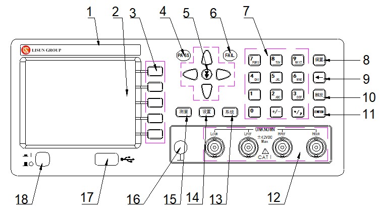
Figure 2-1 Introduction to the Instrument’s Front Panel
The components of the instrument’s front panel (as shown in Figure 2-1) are described as follows:
الماركات والنماذج
ماركة الجهاز، طرازه، نطاق القياس، إلخ.
شاشة LCD
320×240 dot-matrix LCD display that shows configuration information, measurement results, measurement conditions, and more.
مفاتيح لينة
Five soft keys are used to select controls and parameters; the corresponding function definitions are shown to the left of each soft key. The soft key definitions vary depending on the display page.
مؤشر المرور
يتم عرض نتائج الاختبار بواسطة ضوء LED.
زر' التالي
Fast-forward button
مؤشر عطل LED
فشل الاختبار بسبب ضوء LED.
مفاتيح الأرقام
يُستخدم لإدخال الأرقام والمعلومات الأخرى ذات الصلة.
Multifunctional Use of the Offset Keys (Screenshot Key, Unlock Key, ESC Key)
When entering a filename, you can end the input using the numeric keypad.
When a USB flash drive is connected (and “USB flash drive available” is displayed at the bottom of the instrument), press the Bias button to copy the current screen.
The instrument does not have a bias function.
When the instrument is controlled via host computer commands, the entire keyboard on the instrument panel is locked; this key serves as the keyboard unlock key.
[←] مفتاح
مفتاح الحذف (BACKSPACE). اضغط على هذا المفتاح لحذف الحرف الأخير من القيمة المدخلة.
[Trigger] key
When the instrument’s trigger mode is set to MAN (Manual), press this button to trigger the instrument to perform a test.
مفتاح [ENTER]
عند إدخال القيم، اضغط على مفتاح [ENTER] لإكمال إدخال البيانات، والتأكيد، وحفظ البيانات المعروضة في السطر السفلي من شاشة LCD.
عند إدخال اسم ملف، اضغط على مفتاح [ENTER] لإنهاء إدخال اسم الملف، وتأكيده، وحفظ اسم الملف المعروض في السطر السفلي من شاشة LCD.
نهاية الاختبار (غير معروفة)
موصل اختبار رباعي الأطراف. يُستخدم للتوصيل بجهاز اختبار رباعي الأطراف أو كابل اختبار لقياس الجهاز قيد الاختبار.
محرك التيار العالي الجانب (Hcur)؛
أخذ عينات الجهد العالي (Hpot)؛
أخذ عينات الجهد المنخفض (Lpot)؛
محرك التيار المنخفض (Lcur).
[System] Menu Key
Press the [System] button to go to the “System Settings” page.
[Settings] Menu button
Press the [Settings] button to enter the main test settings menu.
[Measurement] Menu Button
Press the [Measure] button to enter the “Component Measurement Display” page.
Chassis Grounding Terminal
This terminal is connected to the instrument housing. It can be used for protective or shielding Grounding connections.
منفذ USB المضيف
تُستخدم لتوصيل ذاكرة فلاش USB.
مفتاح الطاقة (POWER)
اضغط على هذا الزر لتشغيل الطاقة أو إيقاف تشغيلها.
2.3 Rear Panel: Names and Functions of Each Component
The rear panel of the instrument is shown in Figure 2-2.
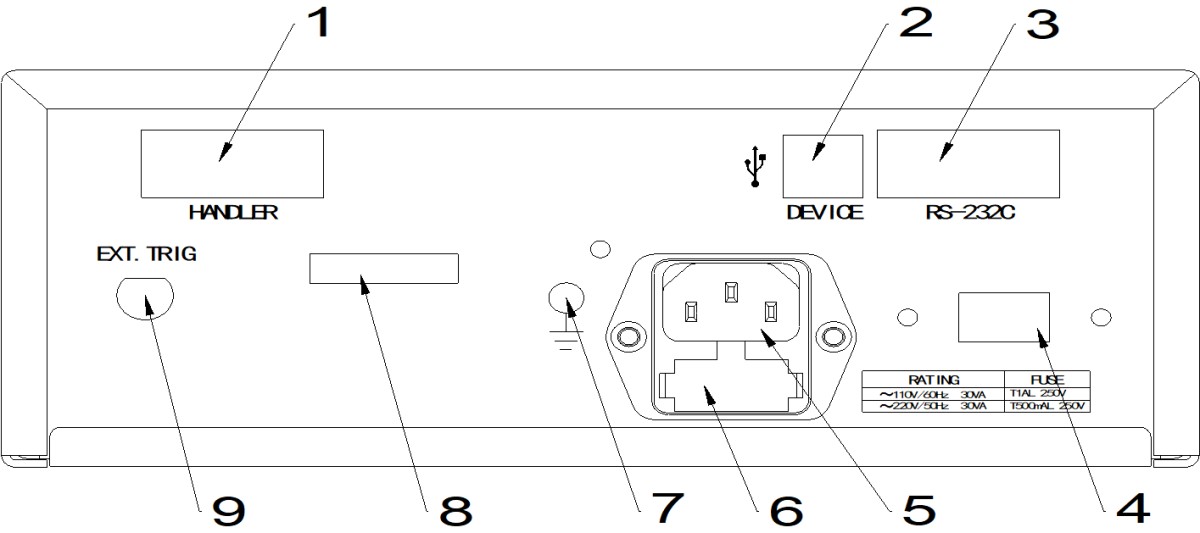
Figure 2-2: Introduction to the Instrument’s Rear Panel
The components of the instrument’s rear panel (as shown in Figure 2-2) are described as follows:
1-HANDLER Port (selectable between 1-stage sorting or 3-stage sorting)
The HANDLER interface makes it easy to set up an automated test system and perform automated testing; it is widely used in automated factory production lines. The instrument uses this interface to output range comparison results and communication signals, and also receives the “Start” signal through this interface.
2-USBDEVICE Interface
عندما يتم ضبط وضع الناقل على USBTMC، يعمل هذا المنفذ كواجهة USBTMC.
When the bus mode is set to USBCDC, this port functions as a USBCDC interface.
When the bus mode is set to USBHID, this port functions as a USBHID interface.
3-RS232واجهة تسلسلية C
You can use this interface to control the instrument.
4-110V/220V Voltage Selector Used to switch between 110V and 220V AC voltage inputs.
5-Power Outlet Used to connect to an AC power source.
6-Fuse Holder
Used to install a power fuse to protect the instrument; switching the direction of the fuse core allows for 110V/220V operation.
Warning: Before turning on the power, make sure the fuse setting matches the supply voltage range.
Grounding This terminal is connected to the instrument’s chassis. It can be used for protective or shielding Grounding connections.
8. Instrument Barcode Area
9-EXT. TRIG Input
عندما يتم ضبط وضع تشغيل الجهاز على التشغيل الخارجي (EXT)، يمكن استخدام هذه الواجهة لتشغيل الجهاز لإجراء القياس.
2.4 Basic Operation Guide
The basic operation of the instrument is as follows:
Use the menu buttons ([Measure], [Settings], [System]) and the corresponding soft keys to select the page you want to display.
Component Test Main Menu Button [Measure]
Used to access the component (LCRZ) measurement display home screen. This key serves as the entry point for the capacitance, resistance, inductance, and impedance measurement menus.
Test Settings Main Menu Button [Settings]
This button serves as the starting point for accessing the test settings and extreme settings interfaces.
System Settings Main Menu Button [System]
Used to access the System Settings home page. This key serves as the starting point for accessing the System Settings and Test Configuration sections.
Use the arrow keys ([←][↑][→][↓]) to move the cursor to the field you want to set. When the cursor hovers over a field, the cursor area will turn yellow. A “field” is an area where you can set the value corresponding to the cursor’s position.
The soft key functions corresponding to the area where the cursor is currently located will be displayed in the “Soft Key Area.” Press the corresponding soft key to select the associated function.
The number keys, the [BACKSPACE] key, and the [ENTER] key are used for data entry; pressing the [ESC] key simultaneously exits data entry mode.
When a numeric key is pressed, the soft-key area will display the available unit soft keys. You can press a unit soft key or the [ENTER] key to complete data entry. When you use the [ENTER] key to complete data entry, the unit of measurement will be the default unit for the corresponding field parameter: P, Hz, V, or A. For example, the default unit for voltage is V.
2.5 Startup Guide
If the user set a startup password before the last shutdown, the instrument will prompt “Please enter the password:” upon startup. The instrument’s default startup password is: 2786.
3. Performance and Testing
وظائف قياس 3.1
3.1.1 Measurement Parameters and Symbols
C: Capacitor L: Inductor
R: Resistance Z: Impedance Y: Admittance
X: Reactance B: Admittance G: Conductance
|Z|: Modulus of impedance |Y|: Modulus of admittance
D: Loss : Phase angle Q: Quality factor
Rs: Equivalent Series Resistance (ESR)
Rp: Equivalent parallel resistance
3.1.2 Measurement Combinations
Table 3-1: Measurement Parameter Combinations
| معلمات الرئيسي | Z, Y | ل، ج | R | G |
| Subparameters | (deg degrees), (rad radians) | D, Q, RS, RP, G | X | B |
3.1.3 Test Parameters and Accuracy
The test parameters are: L, C, R, |Z|, D, Q, G, B, and X.
The test accuracy is: 0.25%–0.05%.
Special Note: For detailed information, please refer to the instrument specifications. Testable parameters and accuracy may vary depending on the model.
3.1.4 Mathematical Operations
Absolute deviation (ΔABS) and percentage deviation (Δ%) of the measured value from a programmable nominal value, and direct reading calculations.
3.1.5 Equivalent Methods
Parallel, Series
3.1.6 Measurement Range
Automatic, Manual (Hold, Increase, Decrease)
3.1.7 مشغل
Internal, External, Manual, Automatic, Bus
Internal: Measures a continuous stream of test items and displays the results
Manual: Press the “START” button on the panel to perform a single measurement and display the result; the meter remains in standby mode at all other times.
External: After the HANDLER instrument interface board receives a “start” signal from an external source, it performs a single measurement and outputs the measurement result, then returns to the standby state.
Automatic: When the test probes make contact with the device under test, the instrument automatically triggers a single test and displays a test result.
Bus: When a trigger command is sent from the bus, the instrument is triggered to perform a test.
3.1.8 Delay Time
Delay Time: The time from the measurement trigger to the start of the measurement. Programmable from 0 to 60 seconds in 1-millisecond increments.
3.1.9 Test-End Method
A four-terminal measurement method is used.
HD (Hcur): Upper current limit; LD (Lcur): Lower current limit
HS (Hpot): High-side voltage LS (Lpot): Low-side voltage
3.1.10 Measuring Speed
Fast: Approximately 10–30 times per second
Medium speed: approximately 5–20 times per second
Slow: Approximately 1.5–6 times per second
At medium and high speeds, speed measurement accuracy decreases when the frequency is less than 1 kHz.
Special Note: For detailed information, please refer to the instrument specifications. Test speeds may vary slightly depending on the model.
متوسط 3.1.11
255 programmable.
3.1.12 Number of Digits Displayed
5 digits, maximum display value 99999
3.2 Test Signals
3.2.1 Test Signal Frequency
The test signal is a sine wave, with a frequency accuracy of 0.02 percent.
The test frequency range is 50 Hz to 100 kHz.
Special Note: For detailed information, please refer to the instrument specifications. The testable frequency range varies by model.
3.2.2 Signal Modes
Program the test voltage on the measurement display page. During measurement, the voltage at the measurement terminals may be lower than the set voltage, depending on the impedance of the device under test.
3.2.3 Test Signal Levels
The instrument’s test levels are 0.1 Vrms, 0.3 Vrms, and 1.0 Vrms.
Special Note: For detailed information, please refer to the instrument specifications. The testable voltage range varies depending on the model.
3.2.4 Internal Resistance Mode
Signal Source Output Impedance Modes: 30 Ω, 100 Ω
Special Note: For detailed information, please refer to the instrument specifications; the internal resistance mode varies depending on the model.
3.2.5 Maximum Measurement Range Display
Table 3-2 Maximum Measurement Range Displayed
| المعاملات | نطاق عرض القياس |
| L | 0.01 nH to 9.9999 kH |
| C | من 0.0001 بيكوفاراد إلى 9.9999 فاراد |
| R, X, Z | من 0.1 ملي أوم إلى 99.999 ميجا أوم |
| Y, B, G | 0.0001 nS to 99.999 S |
| D | 0.0001 إلى 9.9999 |
| Q | 0.0001 إلى 99999 |
| θ | Deg -179.99° to 179.99° Rad -3.14159 to 3.14159 |
3.3 متطلبات السلامة
3.3.1 مقاومة العزل
Under reference operating conditions, the insulation resistance between the power supply terminals and the enclosure shall be no less than 50 MΩ.
Under hot and humid transportation conditions, the insulation resistance between the voltage terminals and the enclosure shall be no less than 2 MΩ.
3.3.2 القوة العازلة
Under reference operating conditions, the power supply terminals and the enclosure shall withstand an alternating voltage of 1.5 kV at a frequency of 50 Hz for a duration of 1 minute. There shall be no breakdown or arcing.
3.3.3 تيار التسرب
The leakage current shall not exceed 3.5 mA (AC rms).
4. [Measurement] Keyboard Guide
4.1 < Component Measurement Display> Page
When you press the [Measure] main button, you will enter the < Component Measurement Display> page, as shown in Figure 4-1.
Special Note: To switch (increase or decrease) the measurement range, use the up and down arrow keys.
The < Component Measurement Display> screen will only show the upper and lower limits and the nominal value when < Test Configuration> is set to ON.
Function Switch Button
Frequency Selection Key Cursor Position Range Number Display Measurement results are displayed at this cursor position; press the number keys 0 and 1 to perform open-circuit and short-circuit calibration. Enter the comparison and sorting settings interface. Nominal values, upper and lower limit settings, and results are displayed. Range Auto and Lock Toggle Key Level Toggle Key
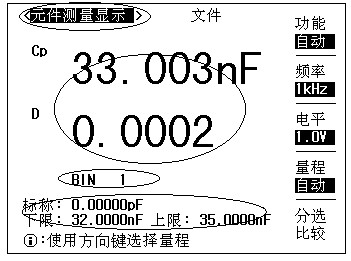
4-1 Instrument < Component Measurement Display> Page
Switch between automatic and locked range modes using the soft keys; use the up and down keys to increase or decrease the range.
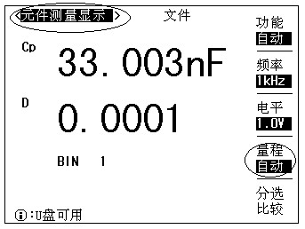
Figure 4-2: Interface without nominal, upper, and lower limit settings displayed
On the < Component Measurement Display> page, the following five soft keys are available:
Functions You can switch between functions (such as Cp_D and Ls_Q).
Frequency You can switch between frequencies (such as 1 kHz and 10 kHz).
Level You can switch between different levels (such as 0.1 Vrms, 0.3 Vrms, and 1.0 Vrms).
Range You can switch between automatic range selection and range lock.
Sorting Comparison Press this soft key to enter the sorting comparison settings screen.
Please note: Depending on the instrument model, the combination of functions, frequencies, and levels may vary slightly, but the setup procedure is similar.
4.2 < Sorting Comparison Settings> Page
The instrument can perform up to five levels of sorting: three levels for合格 (pass), one level for不合格 (fail), and an additional auxiliary level, allowing users to better assess the performance of the tested items.
Press the [Measurement] menu button to enter the < Component Measurement Display> screen, then press the “Sort and Compare” soft key to enter the < Sort and Compare Settings> page. The < Sort and Compare Settings> screen is shown in Figure 4-3.
Enter the upper limit using the numeric keys; enter the lower limit using the numeric keys. Enter the nominal value to clear the settings. Set “Compare” to ON. Change the display mode. Change the sorting method.
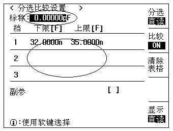
Figure 4-3: < Sorting Comparison Settings> Interface
4.2.1 Nominal Values, Lower Limits, and Upper Limits (Primary and Secondary Parameters)
Used to set the nominal value, lower limit, and upper limit for comparison sorting
4.2.2 Sorting Methods
It includes three sorting methods: Direct Reading (DIR), ABS, and %.
Direct reading: The actual test results are set as the limit values.
ABS: The deviation value of (measured result – nominal value) is set as the limit value.
%: The deviation value, calculated as (actual measurement – nominal value) / nominal value, is set as the limit value.
4.2.3 Comparison Features
When performing a comparison sort, the “Compare” option must be set to ON.
4.2.4 طرق العرض
It includes three display modes: Direct Reading (DIR), ABS, and %.
Direct Reading: The displayed result is the actual test value.
ABS: The result displayed is the deviation between the measured value and the nominal value.
% : Displays the deviation as (measured value – nominal value) / nominal value.
4.2.5 Counting Function
Press the system key to enter the < System Settings> screen, then press the soft key labeled “Test Configuration” to enter the < Test Configuration> screen. Set the counting function to ON to enable it; the counting screen is shown in the figure below.
Stop Counting, Reset Count, Start Counting, Number of Non-Conformities, Number of Conformities, at this cursor position
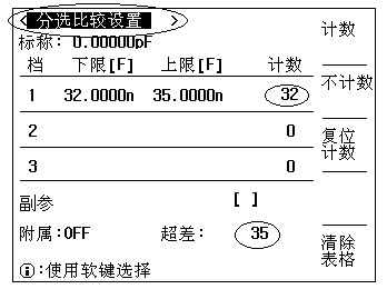
Figure 4-4: Schematic Interface for Sorting Comparison Settings and Counting
The instrument features a bin-counting function. The instrument’s comparison function sorts the test components into different bins, and the number of test components in each bin is counted. The maximum count value that can be displayed on the screen is 999999. When the count exceeds this value, the screen displays “—-”. However, the instrument’s internal counter continues to count normally, so the count value can be read via an interface (such as IEEE 488).
The steps for using the counter function are as follows:
On the < File Count Display> page, move the cursor to the tool area. The following soft keys will appear in the soft-key area of the screen.
Count Press the soft key to start counting and enable the count function. An arrow symbol “►” will appear to the left of “Count.”
Do Not Count Press the soft key to disable counting. The arrow symbol “►” to the left of “Count” will no longer be displayed.
Reset Count: Press the soft key to reset the count. The on-screen prompt area will display: “: Are you sure you want to reset the count?” The soft key area will display the following soft keys:
YES Press the YES soft key to reset all counter values to 0.
NO Press the NO soft key to cancel the trip counter reset operation.
4.3 إدارة الملفات (الملفات)
The instrument can save user-defined parameters as files in its internal non-volatile memory or on an external USB flash drive. The next time the same settings are needed, the user simply needs to load the corresponding file, eliminating the need to reconfigure these parameters. This significantly reduces the time spent on repetitive parameter configuration and improves production efficiency.
Press this soft key to enter the file management interface at the current cursor position.
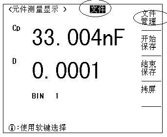
Figure 4-5: Schematic Diagram of the File Management Interface
On any page containing a file field, move the cursor to the file field and press the File Management soft key to access the < File Management> page, as shown in Figure 4-6.
To use the data logging function, first insert a USB flash drive. Once the instrument indicates that the USB flash drive is available at the bottom of the display, enter the “File” menu and press “Start Saving.” Each time the instrument performs a test, it will write one data point to the USB flash drive. The logged data can be opened using Excel or Notepad. When testing is complete, press “End Saving.”The data saving function is typically used in Manual (MAN), External (EXT), and Bus (BUS) modes. In Internal (INT) mode, however, the instrument will continuously write test data to the USB drive.
You can perform file operations on saved files by pressing the corresponding soft key.
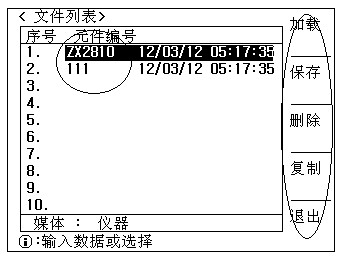
Figure 4-6: File Management Interface
4.3.1 LCR Single-Component Configuration Files (file extension . LCR)
The instrument can manage up to 550 LCR single-component configuration files (with the . LCR file extension). It can store up to 50 different sets of single-component configuration files internally; files numbered higher than 50 are stored on an external USB flash drive (the USB flash drive must be inserted to access files numbered higher than 40).
The instrument supports USB flash drives with the following features:
Compatible with USB 1.0, USB 1.1, and USB 2.0 protocols.
Supports FAT16 and FAT32 file systems (formatted using the Microsoft Windows operating system).
When formatting, be sure to add a volume label (on your computer, right-click the USB drive, select “Properties,” and you’ll see the “Volume Label” field; name it whatever you like).
Please note: The USB flash drive is an optional accessory.
The data stored in an LCR single-group component configuration file (with the . LCR extension) primarily includes:
Setting Parameters on the < Measurement Settings> Page
Test Functions (Parameters)
اختبار القدرات
نطاق الاختبار
مستوى الاختبار
تعويض DC
Average Number of Times
Measurement Delay
Trigger Mode (INT/MAN/EXT)
Automatic Level Control (ON/OFF)
Voltage Level Monitoring (ON/OFF)
Current Level Monitoring (ON/OFF)
Deviation Test A/B Mode (ΔABS/Δ%/OFF)
A/B Deviation Test Reference Values
< File Count Display> Page Settings
Batch Count (Count/Do Not Count)
Configure parameters on the < Advanced List Settings> page
Test Function (Swap Parameters)
Nominal Value (Reference Value)
Comparison Methods (%-TOL/ABS-TOL/SEQ-MODE)
Attachment (ON/OFF)
Comparison Function (ON/OFF)
Upper and lower limits for each bracket
4.3.2 How to Browse Files
The instrument offers three ways to browse files:
Enter a number, then press [ENTER] to jump directly to the file with that number.
Use the [↑] and [↓] arrow keys to scroll through the options one by one.
Use the [←] and [→] arrow keys to navigate page by page.
4.3.3 How to Work with Files
When you enter the < File Management> page, the soft-key display area on the screen will show the following soft keys:
تحميل
Move the cursor or type the number directly and press [ENTER] to navigate to the desired file.
When you press the “Load” soft key, the “YES” and “NO” soft keys will appear, and a prompt will be displayed in the message area.
Press the YES soft key to load the file; press the NO soft key to cancel the file load.
التوفير
Move the cursor or enter the number directly and press the [ENTER] key to navigate to the desired file.
When you press the Save soft key, the YES and NO soft keys will appear, and a message will be displayed in the message area.
Press the YES soft key to load the file. The message prompt area will display “Enter filename:”. Use the numeric keypad and letter soft keys to enter the filename, then press the [ENTER] key to finish. This will save the configuration settings to a file with the specified filename.
Press the “NO” soft key to cancel saving the file.
Special Note: When entering a file name, you can also press the ESC key to cancel the file-saving process.
حذف
Move the cursor or type the number directly and press [ENTER] to navigate to the desired file.
When you press the Delete soft key, the YES and NO soft keys will appear, and a prompt will be displayed in the message area.
Press the YES soft key to delete the file; press the NO soft key to cancel the deletion.
Copy
Press the “Copy” soft key; the message area will display “Enter source file number:”. Press the number keys and then press [ENTER] to confirm; the message area will then display “Enter destination file number:”.
Similar to Step 1, enter the target file number, and the information prompt area will display “Enter the total number of files to copy:”.
Similar to Step 1, enter the total number of files to be copied, and the files will begin copying. At the same time, the information prompt area will display the following message:
5. LCR -> 15. LCR
6. LCR -> 16. LCR
7. LCR -> 17. LCR
.....
All copy is OK!
Special Note: When entering the file number and the total number of files, you can press the ESC key to cancel the file copy process.
Special Note: If the file number you enter is between 50 and 550, the instrument will automatically read from and write to the USB flash drive (the USB flash drive must be inserted at this time; otherwise, the file copy may not complete).
Exit: Press this soft key to exit the file operations interface.
5. [Settings] Key Operations Guide
5.1 < Measurement Settings> Page
Press the [Settings] button on the instrument panel to enter the < Measurement Settings> page, as shown in Figure 5-1.
Press this soft key to access the advanced settings screen
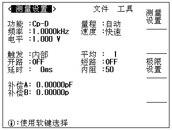
Figure 5-1: < Measurement Settings> Page
On the < Measurement Settings> page, the following measurement control parameters can be configured:
Testing Features (Features)
Test Frequency (Frequency)
Test Level (Level)
Test Range (Range)
Test Speed (Speed)
Trigger Method (Trigger)
Average Number of Times (Average)
Open-Circuit Calibration (Open Circuit)
Short-Circuit Correction (Short Circuit)
Delay Time (Delay)
Output Resistance (Internal Resistance)
Compensation A
Compensation B
File Management (Files)
Support Tools (Tools)
5.1.1 Test Functions
Special Note: Parameter combinations vary by instrument model, but the settings are generally similar.
The instrument can simultaneously measure two parameters of an impedance element within a single cycle: the primary parameters and the secondary parameters. The test results for the primary and secondary parameters are displayed in two lines of large characters. The primary parameters are displayed on the top line, and the secondary parameters are displayed below the primary parameters.
تشمل المعايير الرئيسية ما يلي:
لام (الحث)
ج (السعة)
ص (المقاومة)
|Z| (modulus of impedance)
The main subparameters include:
Rs (Equivalent Series Resistance, ESR)
Rp (Equivalent Series Resistance)
X (Reactance)
Ө (phase angle)
D (Dissipation Factor)
Q (Quality Factor)
The procedure for configuring the measurement functions is as follows:
Use the arrow keys to move the cursor to the function area. The following soft keys will be displayed.
Cp-D
Cp-Q
Cp-G
Cp-Rp
More 1/6
Press the corresponding soft key to select the corresponding function; however, pressing “More 1/6” will bring up the soft-key menu for the next page (2/6) of functions:
Cs-D
Cs-Q
Cs-Rs
More 2/6
Press the corresponding soft key to select the corresponding function. Similarly, you can configure the following functions:
Lp-D
Lp-Q
Lp-G
Lp-Rp
Ls-D
Ls-Q
Ls-Rs
R-X
Z-Өº
Z-Ө r
Rs-Q
Rp-Q
Special Note: When you repeatedly press the “More n/6” soft key (n = 1, 2, 3, 4, 5, 6), the function options described above will be displayed sequentially on the soft key.
5.1.2 Test Frequency
Method 1 for Setting the Frequency:
Move the cursor to the frequency domain. The following soft keys appear in the soft key area on the screen.
↑(++)
This soft key is used for coarse adjustment of the frequency.
(+)
This soft key is used to fine-tune the frequency. Each time you press this key, the frequency increases to the next higher frequency point.
(-)
This soft key is used for fine-tuning the frequency downward. Each time you press this key, the frequency decreases to the next lower frequency point.
↓(–)
This soft key is used for coarse adjustment to decrease the frequency.
Method 2 for Setting the Frequency:
You can select or set the test frequency using soft keys or the numeric keys. When you enter the desired frequency value using the numeric keys, the soft keys display the currently available frequency units (Hz, kHz, and MHz). You can use these unit soft keys to select the unit and enter the data. When you use the [ENTER] key to enter a frequency, the frequency unit defaults to Hz.
Special Note: Frequency combinations vary depending on the instrument model, but the setup is generally similar.
5.1.3 مستويات الاختبار
The instrument’s test level is set based on the root mean square (RMS) value of the test sine wave signal. The frequency of the sine wave signal is the test frequency, which is generated by the instrument’s internal oscillator. You can set either the test voltage or the test current.
Special Note: The test current set on the instrument is the output current value when the test terminals are short-circuited. The test voltage set on the instrument is the output voltage value when the test terminals are open-circuited.
Steps for Setting the Test Level:
There are two ways to set the test signal source level on the instrument. One is to use the soft keys, and the other is to use the numeric input keys.
Use the arrow keys to move the cursor to the level field. The soft-key area on the screen will display the following soft keys.
(++)
Press this soft key to increase the signal source output level.
(+)
Press this soft key to increase the signal source output level.
(-)
Press this soft key to reduce the signal source’s output level.
(-)
Press this soft key to reduce the signal source’s output level.
You can select or set the test level using soft keys or the numeric keys. When you enter the desired level value using the numeric keys, the soft key area displays the currently available level units (mV, V, µA, mA, and A). You can use these unit soft keys to enter both the unit and the data. When you use the [ENTER] key to enter a level value, the unit defaults to V or A.
Special Note: When you need to switch the test level between current and voltage, you must use the numeric keys in combination with the unit soft keys.
5.1.4 Test Range
You can select the appropriate range based on the impedance value of the LCR component being tested.
The instrument has 9 AC test ranges: 10 Ω, 30 Ω, 100 Ω, 300 Ω, 1 kΩ, 3 kΩ, 10 kΩ, 30 kΩ, and 100 kΩ.
Steps for Setting the Test Range:
Use the arrow keys to move the cursor to the range field. The screen will display the following soft keys.
AUTO: This soft key is used to set the range to AUTO mode.
HOLD This soft key is used to switch the range from AUTO mode to HOLD mode. When the range is set to HOLD mode, the range is locked to the current test range. The current test range is displayed in the range field on the screen.
(+) This soft key is used to increase the range in range lock (HOLD) mode.
(-) This soft key is used to decrease the range in range lock (HOLD) mode.
5.1.5 سرعة الاختبار
The test speed of an instrument is primarily determined by the following factors:
Integration Time (A/D Conversion)
Average Number of Measurements (Average number of measurements per session)
Measurement Delay (Time from Startup to Start of Measurement)
Time when measurement results were displayed
You can choose from three test speeds: FAST, MED, and SLOW.
Special Note: Generally speaking, test results are more stable and accurate when measurements are taken at a slower speed.
Use the arrow keys to move the cursor to the Speed zone; the soft-key area on the screen will display the following soft keys.
FAST Set the test speed to Fast mode
MED Set the test speed to medium mode
SLOW Set the test speed to slow mode
5.1.6 Triggering Methods
Trigger Mode: This field is used to select the instrument’s trigger mode—that is, whether the instrument is set to INT, MAN, AUTO, or EXT trigger. Move the cursor to the Trigger Mode field, and the following soft keys will appear:
MAN Set the trigger mode to manual
INT Set the trigger mode to internal trigger
AUTO Set the trigger mode to automatic
EXT Set the trigger mode to “External Trigger”
When the trigger mode is set to MAN, each press of the [TRIGGER] button on the front panel causes the instrument to perform one test.
When the trigger mode is set to INT, the instrument performs continuous, repeated tests.
When the trigger mode is set to AUTO, the instrument will automatically perform one test when the product under test is connected to the test terminals.
When the trigger mode is set to EXT, the instrument performs a test each time the HANDLER interface receives a pulse trigger signal.
When the trigger mode is set to BUS mode, the instrument performs a test each time the instrument interface (such as IEEE 488) receives a “TRIGGER” command.
If the instrument receives a trigger signal while a test is in progress, that trigger signal will be ignored. Therefore, the trigger signal must be sent after the instrument has completed the test.
When you need to trigger the instrument from the optional HANDLER interface, set the trigger mode to EXT.
Special Note: The BUS trigger mode cannot be configured on the instrument’s front panel. To set the instrument to BUS trigger mode, you must send the “TRIGger: SOURce BUS” command to the instrument via an external interface (such as IEEE 488).
5.1.7 Average Frequency
The instrument’s “Average Count” function calculates the average of the results from two or more tests. The average count range can be set from 1 to 255, in increments of 1.
Move the cursor to the Average field. The following soft keys appear in the soft key area on the screen.
↑ (+) This soft key is used to increase the number of measurement averages.
↓ (-) This soft key is used to decrease the number of measurement averages
Users can also enter the average number of times directly using the number keys.
5.1.8 Open-Circuit Calibration
The instrument’s open-circuit calibration function eliminates errors caused by stray admittances (G, B) in parallel with the component under test. See Figure 5-2. Open-circuit calibration includes full-frequency open-circuit calibration using the insertion method and single-frequency open-circuit calibration performed at specified frequency points. For single-frequency open-circuit calibration, please refer to the schematic diagram in Figure 4-2.
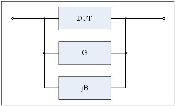
Figure 5-2 Stray Admittance
Turn on open-circuit calibration Turn off open-circuit calibration Press this soft key to perform a full-range open-circuit zeroing
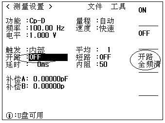
Figure 5-3: Schematic Diagram of the Open-Circuit Calibration Function
Special Note: When performing an open-circuit calibration, connect the test fixture to the instrument’s test terminal. The fixture should be open-circuited and not connected to any device under test.
ON
Press the ON soft key to enable open-circuit correction; the instrument will perform open-circuit correction calculations during subsequent tests.
يوم عطلة
Press the OFF soft key to disable the open-circuit correction function. Open-circuit correction calculations will no longer be performed during subsequent measurements.
Clear the path across all frequencies
Press the soft key to perform a full-range open-circuit calibration; the instrument will measure the open-circuit admittance (capacitance and inductance) at all testable frequency points. The full-range open-circuit calibration takes approximately 15 seconds. During the full-range open-circuit calibration, the following soft keys are displayed:
يستسلم
This soft key stops the current open-circuit calibration test. The original open-circuit calibration data remains unchanged.
5.1.9 Short-Circuit Correction
The instrument’s short-circuit calibration function is primarily designed to eliminate errors caused by parasitic impedance (R, X) in series with the device under test; the equivalent circuit of the parasitic impedance is shown in Figure 5-4.

Figure 5-4 Parasitic Impedance
Special Note: When performing a short-circuit calibration, connect the test fixture to the instrument’s test terminals and simultaneously short-circuit the test fixture using a shorting jumper.
ON
Press the ON soft key to enable short-circuit correction; short-circuit correction calculations will be performed during subsequent tests.
يوم عطلة
Press the OFF soft key to disable the short-circuit correction function. Short-circuit correction calculations will no longer be performed during subsequent measurements.
Short-Circuit Full-Range Clear
Press the soft key to perform a full-frequency short-circuit calibration; the instrument will measure the short-circuit parasitic impedance (resistance and reactance) at all testable frequency points. The full-frequency short-circuit calibration takes approximately 15 seconds. During the full-frequency short-circuit calibration, the screen displays the following soft keys.
يستسلم
This soft key stops the current short-circuit calibration test. The original short-circuit calibration data remains unchanged.
Press this soft key to perform a short-circuit full-range reset, turn off the short-circuit calibration function, or turn on the short-circuit calibration function.
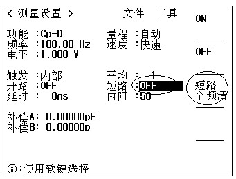
Figure 5-5: Schematic Diagram of the Short-Circuit Calibration Function
5.1.10 Delay Time
Instrument trigger delay refers to the time interval between when the instrument is triggered and when measurement begins. The delay function allows you to set the trigger delay time. The trigger delay can be set within a range of 0 s to 60 s, in 1-millisecond increments.
The procedure for setting the trigger delay is as follows:
Move the cursor to the time domain.
Use the number keys to enter the delay time. After pressing a number key, the following unit soft keys appear in the soft key area on the screen:
msec Press this soft key to set the default input unit to milliseconds
sec Press this soft key to set the default unit of measurement to seconds
Users can also press [ENTER] to finish entering numbers.
Special Note: The trigger delay function is particularly useful when the instrument is used in an automated test system. After the instrument is triggered via the HANDLER interface, the trigger delay ensures that the device under test makes reliable contact with the test terminals.
5.1.11 Output Resistance (Internal Resistance)
The instrument offers up to four selectable signal source impedance modes: 30 Ω and 100 Ω. To ensure data comparability with other tester models when testing inductors and MLCC capacitors, it is essential to use the same signal source impedance mode as those models.
30 Ω is comparable to: 107X/GR1689
100 Ω is comparable to: HP4284A/E4980/chroma3250
Move the cursor to the internal resistance field. The following soft keys appear in the soft key area on the screen.
30 Ω Set the output resistance to 30 Ω
100 Ω Set the output resistance to 100 Ω
Special Note: For detailed information, please refer to the instrument specifications; the internal resistance mode varies depending on the model.
5.1.12 Compensation Function
Because the parameters of the device under test vary with conditions such as temperature and frequency, it may sometimes be necessary to compensate for the test results. The compensation function can be applied to primary parameters, secondary parameters, or both primary and secondary parameters simultaneously.
The process for setting the compensation value is as follows:
Move the cursor to the Compensation A or Compensation B field: Use the numeric keypad to enter the value for Compensation A (primary parameter) or Compensation B (secondary parameter) directly.
If the value of compensation A or compensation B is not zero, the result displayed will be the measured value minus the compensation value.
Move the cursor to the compensation settings field and use the numeric keys to enter the values for Compensation A and Compensation B.
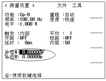
Figure 5-6: Schematic Interface of the Compensation Function
5.1.14 Auxiliary Tools (Tools)
There are two soft keys available in the Tools area:
System Reset: Press this soft key to reset the system.
Clear Settings: Press this soft key to restore the default settings.
5.1.13 إدارة الملفات (الملفات)
Please refer to Section 4.3, “File Management (Files).”
5.2 < Limit List Settings> Page
The instrument can sort items into up to five categories: three “pass” categories, one “fail” category, and one additional category.
Press the [Settings] menu key, then press the “Limit Settings” soft key to enter the < Limit List Settings> page, as shown in Figure 5-7.
Set the upper and lower limits for the channel comparison, select the comparison method (%), ABS, or direct reading, and turn on the channel comparison switch.
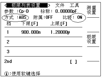
Figure 5-7: < Limit List Settings> Page
The instrument can be configured with three limit ranges for primary parameters and one limit range for a secondary parameter. Test results can be sorted into up to five bins (BIN1 through BIN3, BIN OUT, or an auxiliary bin). If a test piece’s primary parameters fall within the limit ranges for BIN1 through BIN3, but its secondary parameters do not, the test piece is sorted into the auxiliary bin. On the < Limit List Settings> page, you can configure the limit parameters for the following comparison functions:
Special Note: When the instrument is used with the HANDLER interface as part of an automated test and sorting system, its comparison function truly demonstrates its superiority.
5.2.1 Swapping Parameters
The parameter swap function allows users to swap the primary and secondary parameters in the parameter field, providing greater flexibility in using the instrument. For example: When the test parameters are Cp-Q, the parameter swap function changes the test parameters to Q-Cp. In this case, three pairs of comparison limit values can be set for Q, while only one pair of comparison limit values can be set for Cp.
Move the cursor to the parameter field, and the on-screen soft-key area will display the following soft keys:
Swap Parameters: Press this soft key to swap the primary and secondary parameters.
5.2.2 Sorting Methods
It includes three sorting methods: Direct Reading (DIR), ABS, and %.
Direct reading: The actual test results are set as the limit values.
ABS: The deviation value of (measured result – nominal value) is set as the limit value.
%: The deviation value, calculated as (measured result – nominal value) / nominal value, is set as the limit value.
Special Note: If upper and lower limits have already been set, you must first clear the limit list before changing the limit mode.
In tolerance mode, the setting of limit values is relatively flexible; the lower limit does not necessarily have to be less than the nominal value, and the upper limit does not necessarily have to be greater than the nominal value. The limit ranges for each range may be discontinuous or may overlap.
When the limit value is set to tolerance mode, the error ranges should be set in ascending order whenever possible. If the error range set for BIN 1 is the largest, all test pieces will be sorted into BIN 1, which is not conducive to detailed data categorization.
5.2.3 Auxiliary File ON/OFF (Auxiliary)
When you need to filter secondary parameters, you can set their limit values in the upper and lower bound settings for “2nd.”
There are three scenarios regarding the sorting of secondary parameters, as described below:
On the < Advanced List Settings> page, if no upper and lower limits are set for the secondary parameters, no sorting based on those parameters will be performed.
On the < Extreme List Settings> page, the upper and lower limits for the secondary parameters have already been set. However, the “Attachment” feature is set to OFF.
At this point, only devices that meet the secondary parameter requirements will have their primary parameters sorted according to the sorting limits. If the secondary parameters do not meet the requirements, all such devices will be sorted into the BIN OUT category, even if their primary parameters fall within the set limits.
On the < Extreme List Settings> page, the upper and lower limits for the secondary parameters have already been set. Additionally, the “Attachment” feature is set to ON.
If the primary parameter is outside the set tolerance range, the part will be sorted into the BIN OUT category. If the primary parameter of the part under test is within the tolerance range but its secondary parameter is not, the part will be sorted into the secondary category.
Special Note: When only the lower limit value is set for the secondary parameter and the auxiliary grade is set to ON, if the main parameter of the workpiece falls within the limit range but the secondary parameter value is less than or equal to the lower limit value of the secondary parameter, the workpiece is sorted into the auxiliary grade. Similarly, when only the upper limit value is set for the secondary parameter and the “Supplementary Class” setting is ON, if the main parameter of the test piece falls within the set limit range and the secondary parameter value is greater than or equal to the upper limit value of the secondary parameter, the test piece is sorted into the supplementary class.
5.2.4 Comparator Function ON/OFF (Comparison)
Move the cursor to the comparator function area, and the following soft keys will appear in the soft key display area on the screen:
ON Press this button to enable the comparison feature
OFF Press this button to turn off the comparison feature
The instrument can be configured with three limit ranges for primary parameters and one limit range for a secondary parameter. Test results can be sorted into up to four bins (BIN1 through BIN3 and BIN OUT). If a test piece’s primary parameters fall within the limits of BIN1 through BIN3 but its secondary parameters do not, the test piece is sorted into the auxiliary bin.
Special Note: When the instrument is used with the HANDLER interface as part of an automated test and sorting system, its comparison function truly demonstrates its superiority.
5.2.5 Upper and Lower Limits for Each Range
The instrument allows you to set the bin limits for three primary parameters and one secondary parameter. Test results can be sorted into up to four bins (BIN1 through BIN3 and BIN OUT). The upper and lower limits for these primary parameters can be set within the upper and lower limit setting ranges for BIN1 through BIN3. The upper and lower limits for the secondary parameter can be set within the upper and lower limit setting range for “2nd.”
The process for setting the upper and lower limits is as follows:
Move the cursor to the tool field and press the soft key to clear the currently set file limits. If no upper or lower limits have been set, you can skip this step.
Set the test parameters for the comparison function, the nominal values, and the limit modes for the main parameters.
Use the numeric keys in the lower limit setting area for Range 1 to enter the lower limit value for Range 1. After entering the data, you can use the subscript soft keys (p, n, µ, m, k, M, *1) to enter limit values instead of the [ENTER] key. When using the [ENTER] key to enter limit values, the unit defaults to the same unit as the last limit entry. When you press soft key *1, the default units for limit values are F, H, or Ω. After entering the limit values for Range 1 in the lower limit field, the lower limit for Range 1 is automatically set to – (absolute limit), and the upper limit for Range 1 is automatically set to + (absolute limit).
The cursor automatically moves to the lower limit setting field for Channel 2. Repeat Step 1 until you have entered the limit values for Channel 9. The cursor will then automatically move to the lower limit setting field for Channel 2.
After entering the lower limit for the secondary parameter, the cursor will automatically move to the upper limit input field for “2nd.”
Enter the upper limit for the secondary parameter.
5.2.6 إدارة الملفات (الملفات)
Please refer to Section 4.3, “File Management (Files).”
5.2.7 Auxiliary Tools (Tools)
Move the cursor to the tool settings area; the on-screen soft-key display area will show the following soft keys:
Clear Table: Press this key to clear all file limit values on the current page.
Special Note: If upper and lower limits have already been set, you must clear the limit list before changing the limit mode.
6. [System] Primary Key Operation Guide
Under the [System] main tab, there are two main interface screens: the < System Settings> screen and the < Test Configuration> screen.
6.1 < System Settings> Page
Press the [System] button on the instrument to go directly to the < System Settings> screen, as shown in Figure 6-1.
You can configure the relevant functions by adjusting the corresponding settings.
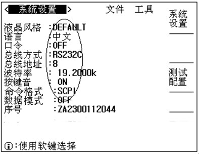
Figure 6-1: < System Settings> Screen
The System Settings page is primarily used to configure functions related to instrument extensions that are not related to test performance. It mainly includes:
LCD style, language, password, bus mode, bus address, baud rate, keypress tones, etc.
6.1.1 LCD Style
The LCD Style setting field is used to set the instrument’s current display style. Move the cursor to the LCD Style setting field to display the following available soft keys:
CLASSIC Sets the instrument display style to CLASSIC mode.
DEFAULT Sets the instrument display style to DEFAULT (system default) mode.
شنومكس اللغة
The language setting field is used to set the instrument’s current operating language. Move the cursor to the language setting field, and the following soft keys will be displayed:
Chinese Set the current operating language to Chinese.
ENGLISH Set the current operating language to English.
6.1.3 كلمة المرور
To distinguish between users’ access privileges for the instrument, a password-protected mode has been configured. Move the cursor to the password setup field to display the following available soft keys:
OFF Press this soft key to disable password protection.
Lock System: Press this soft key to enable the lock system’s password protection features, including file protection and the startup password.
Lock File This soft key is used to enable the file lock protection feature.
Change Password: Press this soft key to access the password change function. The password change process is as follows:
أدخل كلمة مرورك القديمة
أدخل كلمة مرور جديدة
Confirm the new password. If the entry is correct, the password change will be completed.
Important Note: When disabling password protection, locking a file, or locking the system, you must first enter the old password.
6.1.4 Bus Mode
Bus Mode is used to set the instrument’s currently available bus communication mode. The instrument supports five bus modes: RS232S (optional), GPIB (optional), USBCDC (optional), USBTMC (optional), and USBHID (optional).
Move the cursor to the bus mode settings area, and the following soft keys will be displayed:
RS232S Press this soft key to select the RS232S interface as the bus mode.
GPIB Press this soft key to select GPIB as the bus mode.
USBCDC Press this soft key to select the USBCDC interface as the bus mode.
USBTMC Press this soft key to select the USBTMC interface as the bus mode.
USBHID Press this soft key to select the USBHID interface as the bus mode.
Special Note: The USBCDC, USBTMC, and USBHID interfaces all share the USB DEVICE interface. When the bus mode is USBCDC, the USB DEVICE interface functions as the USBCDC interface; When the bus mode is USBTMC, the USB DEVICE interface functions as the USBTMC interface; when the bus mode is USBHID, the USB DEVICE interface functions as the USBHID interface.
6.1.5 Bus Address
The Bus Address field is used to set the GPIB interface bus address for the current instrument. This setting is effective only when the Bus Mode selector is set to GPIB mode. Move the cursor to the Bus Address field, and the screen will display the following available soft keys:
(+) This soft key is used to increase the device’s bus address.
(-) This soft key is used to decrease the device’s bus address.
Special Note: The GPIB bus address range is 1–32.
6.1.6 Baud Rate
The baud rate is used to select the baud rate for the instrument’s RS-232 interface. The instrument’s baud rate can be set within the range of 9.600 k to 115.200 k. When you move the cursor to the baud rate setting field, the following soft keys will appear:
(+) This soft key is used to increase the baud rate of the instrument’s RS-232 interface.
(-) This soft key is used to decrease the baud rate of the instrument’s RS-232 port.
6.1.7 Keypress Sounds
The Key Sound setting field is used to turn key sounds on or off. Move the cursor to the Key Sound setting field:
ON Turn on button sounds.
OFF Turn off keyboard sounds.
6.1.8 CMD Format (Command Format)
The “CMD Format” setting field allows you to specify whether the RS232 communication format should be the LS2810 format (compatible with the earlier 2810 series) or the SCPI (standard communication format) format. Move the cursor to the “CMD Format” setting field:
SCPI Select the SCPI format (standard communication format) for RS232 الاتصالات.
LS2810 Select the RS232 communication format as the LS2810-compatible format.
Special Note: The LS2810 communication format is only applicable when the bus mode is set to RS232; for all other bus modes, communication uses the SCPI format. Typically, when using the LS2810 communication format, the baud rate should be set to 19.2000 k.
Press this button to select the SCPI communication format. Press this button to select the LS2810-compatible communication format.
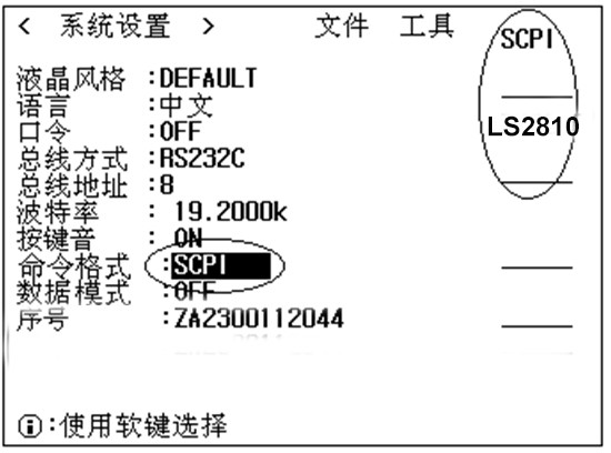
Figure 6-2: CMD Format (Command Format) Function Selection Diagram
6.1.9 RS-232 Send (Data Transmission Mode)
The RS-232 Send setting field is used to configure the RS-232 interface data mode as either unidirectional (receives data only) or bidirectional (allows data to be sent upstream). Move the cursor to the RS-232 Send setting field:
ON Bidirectional (allows data to be sent upstream).
OFF Unidirectional (accepts data only).
Special Note: The Rs232 Send (data transmission mode) is only available when the bus mode is set to RS232 and the CMD Format is set to LS2810; for all other bus modes, communication uses the SCPI communication format.
6.1.10 HTTP (Company Website)
LISUN’s website is www. Lisungroup.com,客户可以登录公司网站了解最新产品信息.
6.1.11 SN (Serial Number)
The Serial Number (SN) field displays the instrument’s serial number.
6.2 < Test Settings> Screen
Press the [SYSTEM] main button on the instrument to go directly to the < System Settings> screen. Then press the “Test Configuration” soft key to enter the < Test Configuration> screen, as shown in Figure 6-3.
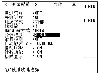
Figure 6-3: < Test Setup> Interface
On the < Test Settings> screen, you can configure settings for pass signals, fail signals, current source, trigger mode, trigger edge, handler mode, sorting mode, and fixture detection.
6.2.1 Through Xunxiang
Use the “Set Alarm via Audible Signal” field to configure the alarm mode when sample measurement results are within specifications. Move the cursor to the “Set Alarm via Audible Signal” field, and the following available soft keys will be displayed:
HIGH LONG Press this soft key to select a high-pitched, long alarm tone
HIGH SHORT Press this soft key to select a high-pitched, short alarm tone
LOW LONG Press this soft key to select a low, long beep.
TWO SHORT Press this soft key to select two low, short beeps.
OFF Press this soft key to turn off the Xunxiang alarm.
6.2.2 Failure Alerts
The “Failure Alarm Settings” field is used to configure the alarm mode when sample measurement results are within specifications. Move the cursor to the “Failure Alarm Settings” field, and the following available soft keys will be displayed:
HIGH LONG Press this soft key to select a high-pitched, long alarm tone
HIGH SHORT Press this soft key to select a high-pitched, short alarm tone
LOW LONG Press this soft key to select a low, long alarm tone
TWO SHORT Press this soft key to select two low, short beeps.
OFF Press this soft key to turn off the failure alert tone.
6.2.3 Trigger Modes
Trigger Mode: This setting field is used to select the instrument’s trigger mode—that is, whether the instrument uses INT, MAN, AUTO, or EXT triggering. Move the cursor to the trigger mode setting field, and the following soft keys will appear:
MAN Set the trigger mode to manual
INT Set the trigger mode to internal trigger
AUTO Set the trigger mode to automatic
EXT Set the trigger mode to “External Trigger”
When the trigger mode is set to MAN, each press of the [TRIGGER] button on the front panel causes the instrument to perform one test.
When the trigger mode is set to INT, the instrument performs continuous, repeated tests.
When the trigger mode is set to AUTO, the instrument will automatically perform one test when the product under test is connected to the test terminals.
When the trigger mode is set to EXT, the instrument performs a test each time the HANDLER interface receives a pulse trigger signal.
When the trigger mode is set to BUS mode, the instrument performs a test each time the instrument interface (such as IEEE 488) receives a “TRIGGER” command.
If the instrument receives a trigger signal while a test is in progress, that trigger signal will be ignored. Therefore, the trigger signal must be sent after the instrument has completed the test.
When you need to trigger the instrument from the optional HANDLER interface, set the trigger mode to EXT.
Special Note: The BUS trigger mode cannot be configured via the instrument’s front panel. To set the instrument to BUS trigger mode, you must send the “TRIGger: SOURce BUS” command to the instrument via an external interface (such as IEEE 488).
6.2.4 Trigger Edge
The “Trigger Edge” setting field is used to select whether the instrument is triggered by a rising edge or a falling edge. Move the cursor to the “Trigger Edge” setting field, and the softkey display area will show the following available softkeys:
Set the instrument to rising-edge triggering

Set the instrument to falling-edge trigger

6.2.5 Handler Pattern
The Handler Mode setting field is used to determine how the last Handler trigger signal is handled. When you move the cursor to the Handler Mode setting field, the following soft keys will appear:
HOLD Press this soft key to select HOLD mode, which means that when the signal is triggered this time, the signal from the previous trigger will be maintained.
CLEAR: Press this soft key to select CLEAR mode, which clears the previous trigger signal upon this trigger.
6.2.6 Bin Sorting (Sorting Mode)
The “Bin Sorting” mode is used to select whether the Handler interface should use 1-stage or 3-stage sorting. For the definition of the Handler interface sorting signals, please refer to the Handler interface documentation. Move the cursor to the “Bin Sorting” setting field:
3 BIN Select the 3-bin sorting mode in the Handler interface.
1 BIN Select sorting mode 1 in the Handler interface.
Select sorting mode 1; select sorting mode 3
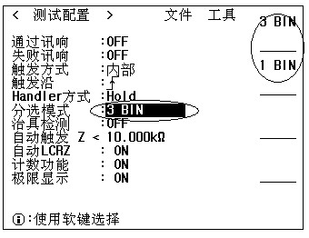
Figure 6-4: Schematic Diagram of the Bin Sorting Function Selection
6.2.7 Fixture CHK (Fixture Inspection)
Fixture CHK is typically used to determine whether the instrument is performing a no-load test or whether the fixture contacts are secure; this feature is generally used only by specific users. If you do not intend to use this feature, simply set the Fixture CHK function to OFF. Move the cursor to the Fixture CHK setting field:
ON Enable the fixture detection function.
OFF Disables the fixture detection function.
Special Note: The fixture detection feature only works when the range comparison feature is enabled.
6.2.8 Auto Trig Z (Automatic Z Trigger)
The “Auto Trigger Z” setting is used to define the threshold at which the instrument automatically triggers a test. When the impedance of the test object is detected to be below this threshold, the instrument will automatically perform the test, making the testing process more intelligent.
Move the cursor to the “Auto-Trigger Z” setting field, press a number on the numeric keypad, and then press ENTER to finish; this allows you to enter limit values.
Special Note: The automatic Z-test feature only works when the trigger mode is set to Automatic (AUTO).
6.2.9 Auto LCRZ (Automatic LCRZ)
The automatic LCRZ function primarily selects the appropriate test mode (Cp_D, Ls_Q, or Z) based on whether the device under test is inductive, capacitive, or resistive. In the automatic LCRZ settings menu, there are two soft keys available:
ON Enable the automatic LCRZ function.
OFF Disables the fixture detection function.
6.2.10 Count Function (Count FUNC)
If the counting function is set to ON, you can count the number of合格 and不合格 items on the sorting comparison settings screen; if the counting function is set to OFF, the counting function is disabled. The counting function is shown in Figure 6-5.
Reset Count Stop Count Start Count Failed Counts Passed Counts At this cursor position
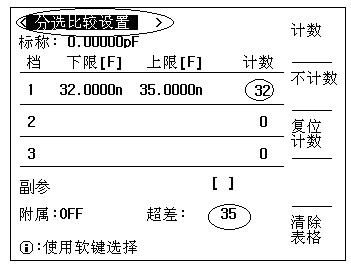
Figure 6-5: Schematic Interface of the Counting Function
6.2.11 Limit Display (Limit DISP)
If the limit display is set to ON, the nominal value, upper limit, and lower limit are displayed on the < Component Measurement Display Screen>; if the limit display is set to OFF, they are not displayed.
7. Remote Control User Guide
The instrument includes a total of five external interfaces: RS232C, GPIB (optional), USBTMC, USBCDC, and USBHID. The instrument can be controlled remotely using any of these external interfaces.
7.1 RS Interface Description
The RS-232 serial communication standard, also known as the asynchronous serial communication standard, where “RS” stands for “Recommended Standard” and “232” is the standard number, is a standard published by the U. S. Electronic Industries Association (IEA). It specifies the transmission of one bit at a time over a single data line. RS-232 interfaces typically come in 9-pin (DB-9) or 25-pin (DB-25) configurations, with the DB-9 being the more commonly used type. Its pin definitions are shown in Table 7-1.
Table 7-1: DB-9 RS-232 Interface Pinout
| دبابيس | تعريف | رمز |
| 1 | كشف الناقل | DCD |
| 2 | استقبال البيانات | RXD |
| 3 | أرسل البيانات | TXD |
| 4 | Data terminal ready | DTR |
| 5 | الأرض إشارة | GND |
| 6 | The data is ready | DCR |
| 7 | إرسال طلب | RTS |
| 8 | Clear Sent Items | CTS |
| 9 | Vibration Alert Display | RI |
The instrument’s serial interface is not strictly based on the RS-232 standard; instead, it uses only three of the wires, providing only a minimal subset. Its greatest advantage is that operating with just three wires is relatively inexpensive, as shown in Table 7-2.
Table 7-2: Instrument RS-232 Signal and Pin Assignment
| دبابيس | تعريف | رمز |
| 2 | استقبال البيانات | RXD |
| 3 | أرسل البيانات | TXD |
| 5 | الأرض إشارة | GND |
The connection between the host PC and the instrument is shown in Figure 7-1.
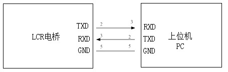
Figure 7-1: Diagram of the Connection Between the PC and the Instrument
The instrument’s RS-232 interface offers a variety of baud rates ranging from 9600 to 115200, with no parity, 8 data bits, and 1 stop bit.
The instrument’s commands (for details, refer to the section on commands) comply with the SCPI standard. After a command string is sent to the instrument, an LF (hexadecimal: 0AH, ASCII: 10) must be sent as the terminating character. The instrument can accept a maximum of 2048 bytes in a single SCPI command string.
7.2 GPIB Interface Description
The IEEE 488 (GPIB) General-Purpose Interconnect Bus is an internationally recognized bus interface for intelligent instruments. IEEE stands for the Institute of Electrical and Electronics Engineers, and 488 is the standard designation. GPIB is an interface standard used to connect computers to peripheral devices that comply with the international standards IEEE 488.1, IEC 625, IEEE 488.2, and JIS C 1901.
A single computer, equipped with a GPIB control card, can perform data acquisition, data transmission, and control functions for one or more instruments, forming an instrument system that makes our testing and measurement work fast, simple, accurate, and efficient. By connecting via GPIB cables, it is easy to configure star, daisy-chain, or hybrid configurations.
The instrument complies with the IEEE 488.2 standard, and the interface board can be inserted into any of the three expansion slots. The control command system is open; users can either use the computer interface provided with the product or write their own programs based on this control command system to achieve their objectives. The control command system supports all instrument functions, meaning that the full range of instrument operations can be performed on the control computer to enable remote control of the instrument.
System Scale That Can Be Achieved with GPIB:
A single GPIB system can connect up to 15 devices.
The connection configuration can be star, linear, or a combination of the two, but a ring configuration is not permitted.
The length of the cables connecting the devices must not exceed 4 m. In a single GPIB system, the total cable length must not exceed 2 m multiplied by the number of connected devices (including the controller), and the total cable length in the system must not exceed 20 m.
The number of connectors connected to a single device must not exceed four; exceeding this limit will subject the connection points to excessive external force, which may cause a malfunction.
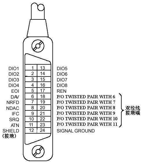
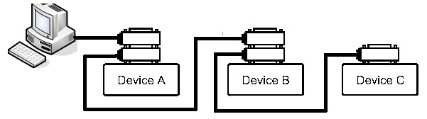
Figure 7-2 GPIB Example System 1
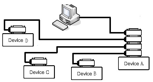
Figure 7-3 GPIB Example System 2
7.2.1 GPIB Interface Functions
The GPIB interface provides access to the test instrument’s various functions; the instrument can transmit, receive, and process data and commands via the bus. The functions of this interface are shown in Table 7-3:
Table 73: Interface Functions
| رمز | ميزات الواجهة | الوظيفة |
| SH1 | Data Source Contacts | Three-Line Connection |
| AH1 | جهة الاتصال بالمستلم | Three-Line Connection |
| T5 | Talking About Features | Send Instrument Information |
| L4 | مهرات الأصغاء | Receive Instrument Information |
| SR1 | طلب خدمة | طلب خدمة |
| RL1 | Long-Distance to Local Call Conversion | Switch Between Local and Remote Control |
| DC1 | Instrument Reset | Send a reset signal |
| رمز | ميزات الواجهة | الوظيفة |
| DT1 | Instrument Triggering | Send a trigger signal |
| C0 | وظائف الرقابة | Send Control Information |
7.2.2 GPIB Bus Address
The address range for the instrument’s GPIB parallel communication interface bus mode is 1–31. For information on setting the address, refer to Section 6.1.5, “Bus Address Settings.”
7.2.3 GPIB Bus Functions
The bus functions of the instrument’s parallel communication interface are implemented by the following commands.
ABORT I/O (IFC) is used to suspend all bus activity, stop receiving messages from the tester, and reset the interface to an idle state.
CLEAR LOCKOUT/SET LOCAL is used to control the instrument, enabling it to enter remote operation mode.
DEVICE CLEAR (SDC or DCL) resets the selected instrument or resets all instruments.
LOCAL (GTL) returns control to the local system, allowing a remote control device—which is acting as a listener—to return to local control.
LOCAL LOCKOUT (LLO) blocks local commands. When this command is executed, the remotely controlled instrument will block local messages upon receiving it.
REMOTE is used to set the instrument to remote control mode.
The SPOLL serial polling command is used to configure the bus address status byte. An 8-bit byte is used to mask and read data to determine the instrument’s operating status.
طلب الخدمة
When the instrument’s controller is executing a task, the instrument can send an SRQ (Service Request) control signal. The SRQ signal can be considered an interrupt; it notifies the controller that the instrument is ready to transmit information or that an error has occurred. When the instrument sends the SRQ signal, it also sets the status byte to 6 bits. Bit 6 is the RQS (Request Service) bit, which sometimes functions as a status bit during roll call connections. When the instrument is in serial roll call mode, it clears the RQS bit and the SRQ line. Each bit of the status byte can trigger an SRQ service request. Users can mask the status byte to determine which bit caused the instrument to set the SRQ line. For details, see “Status Byte.”
TRIGGER (GET) triggers a bus command. This command can be sent to the selected instrument or to all instruments designated as listeners. The instrument must first be designated as a listener, and then the bus trigger mode must be set to trigger mode before sending the trigger message.
7.3 USBCDC Interface
7.3.1 USBCDC Interface Configuration and Installation
When the bus mode is set to USBCDC bus (see Section 6.1.4), the USB DEVICE is emulated as a serial port (Vcom), allowing users to communicate with the instrument via the USB interface using an RS-232-like communication format. This resolves the issue where some computers, lacking a serial port, cannot communicate with the instrument using the RS-232 communication protocol.
USBCDC Interface Installation Instructions: Use a dedicated USB cable to connect the USB DEVICE port on the rear panel of the instrument to the USB port on your computer.
7.3.2 Installing the USBCDC Driver
If you are using the USB DC interface and connecting to a computer with a dedicated USB cable, the driver installation wizard will appear the first time you connect to the computer. Select “Install from a list or specific location,” as shown in Figure 7-4.
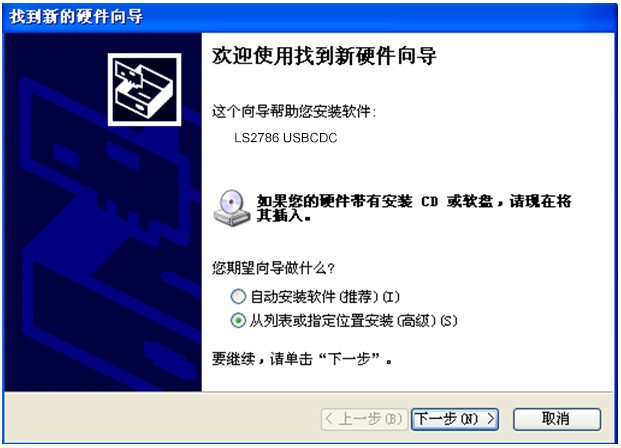
Figure 7-4 Driver Installation Wizard
You need to install the Vcom.inf driver file provided by the manufacturer. Select “Include this location in the search” to locate the path where the Vcom.inf file is located, as shown in Figure 7-5.
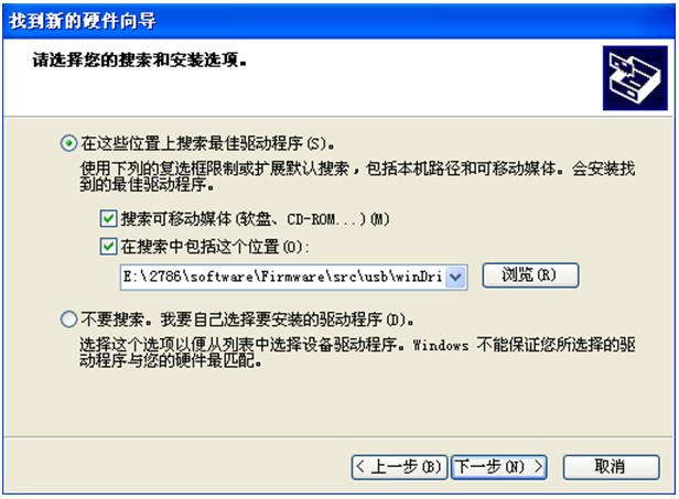
Figure 75: Specifying the Driver File Path
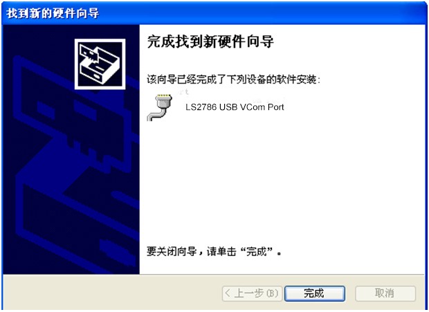
Figure 76: USBCDC Driver Installation Complete
Once the driver is installed, users will see “LS2786 USB VCom Port” in the computer’s Device Manager. As shown in Figure 7-7:
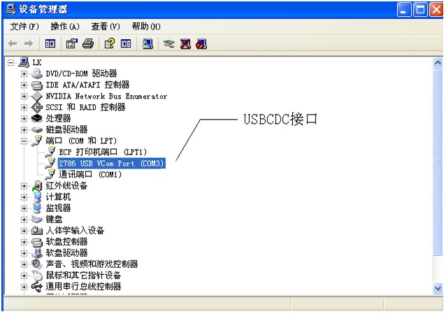
Figure 77: Device Manager showing the LS2786 USB VCom Port
In this case, the LS2786 USB VCom Port functions as a serial port. When a PC does not have a serial port, users can use their existing serial-based communication software in this mode, just as they would with a virtual serial port connected via USB.
7.4 USBTMC Interface
USBTMC stands for USB Test & Measurement Class. USBTMC is a communication protocol built on top of USB. With USBTMC, you can control your USB-connected instruments just as you would control GPIB-connected instruments; from the user’s perspective, controlling USBTMC-based USB instruments is identical to controlling GPIB-based instruments.
The instrument’s USBTMC interface is compatible with USB 2.0, USBTMC 1.0, and the USBTMC-USB488 protocol; users can control and operate the instrument via the USBTMC interface.
7.4.1 USBTMC Interface Configuration and Installation
When the bus mode is set to USBTMC bus (see Section 6.1.4), the USB DEVICE is configured as a USBTMC interface.
USBTMC Installation Instructions: Use a dedicated USB cable to connect the USB DEVICE port on the rear panel of the instrument to the USB port on your computer.
7.4.2 Installing the USBTMC Driver
Important Note: Before installing the USBTMC driver, you must first install the VISA software provided by LISUN.
If you are using the USBTMC interface and connecting it to the computer with a dedicated USB cable, the driver installation wizard will pop up the first time you connect to the computer. Select “Install the software automatically,” click “Next,” and the driver will be installed automatically, as shown in Figures 7-8.
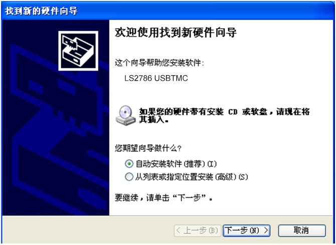
Figure 7-8 USBTMC Driver Installation Wizard
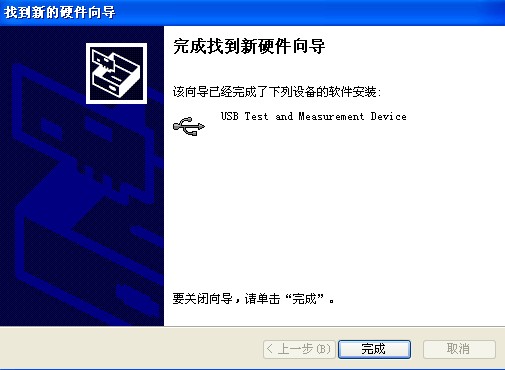
Figure 7-9 USBTMC Driver Installation Successful
Once the driver is installed, users will see “USB Test and Measurement Device” in the computer’s Device Manager, as shown in Figure 7-10:
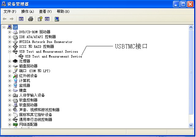
Figure 710: The USBTMC interface displayed in Device Manager
8. دليل مستخدم واجهة المعالج
The instrument provides users with a Handler interface, which allows for the convenient construction of automated component sorting systems. When the instrument is used in an automated component sorting and testing system, this interface provides interaction signals with the system and output signals for sorting results. The instrument’s Handler interface offers two sorting modes: Upon startup, the default settings are P3 (3-bin sorting, with three primary parameters and one secondary parameter) and P1 (1-bin sorting, with one primary parameter and one secondary parameter). For specific configuration details, refer to Section 6.2.6, “Bin Sorting (Sorting Mode) Settings.”
8.1 تعريف واجهة المعالج
مواصفات إشارة الخرج: خرج نشط منخفض المستوى، ذو مجمع مفتوح، معزول بصريًا.
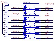
Figure 8-1 Definition of the Handler Interface
When Bin Sorting is used for 3-tier sorting, the sorting flowchart is shown in Figure 8-2:
Table 8-1 Definitions of the 3-Level Sorting Signals
| موقف القدم | شرح المميزات: |
| 1 | /NG (D/QNG) indicates a failure signal; the output is active low. |
| 2 | /P1 هو منتج من الدرجة الأولى يفي بالمواصفات؛ الناتج منخفض وصحيح. |
| 3 | /P2 indicates a second-grade pass, with low output effectiveness |
| 4 | المنتج /P3 هو منتج من الدرجة 3 ذو فعالية إنتاج منخفضة |
| 5 | / WAIT (Busy) output, active low. This signal can be used to control the operation of external mechanical handling equipment during instrument testing; when this signal is active, the instrument is performing measurements and calculations. |
| 6 | /EOC (A/D End): Output, active low. When this signal is output, the measurement (A/D conversion) for the current device under test has been completed, although calculations may still be in progress. When this output is high, good contact between the test probe and the current device under test must be ensured; when it is low, external mechanical equipment is permitted to move the next test device to the test probe in preparation for the next measurement. |
| 7 | /START (Start): Input; valid only if it is a falling edge and the low-level duration is greater than 2.5 ms. This signal is supplied externally to the HANDLER’s input terminal. |
| 8 | EXTV External Input Power Supply Terminal (The instrument is connected to the external power supply by default) |
| 9 | COM Interface Output Ground Pin |
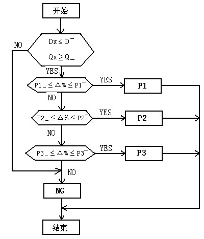
Figure 8-2 3-Bin Sorting Flowchart
When Bin Sorting is used for single-tier sorting, the sorting flowchart is shown in Figure 8-3:
Table 8-2 Definitions of Sorting Signals for Level 1
| موقف القدم | شرح المميزات: |
| 1 | /NG (D/QNG) is a signal indicating that the auxiliary parameters are out of specification; the output is active-low. |
| 2 | /PASS is the main parameter pass signal; the output is active-low |
| 3 | /HI: High on the main parameter, output is active low |
| 4 | /LO: High when the main parameter is exceeded; output is active low |
| 5 | / WAIT (Busy) output, active low. This signal can be used to control the operation of external mechanical handling equipment during instrument testing; when this signal is active, the instrument is performing measurements and calculations. |
| 6 | /EOC (نهاية التحويل التناظري/الرقمي): خرج، فعال عند انخفاض الجهد. عند إخراج هذه الإشارة، يكون قياس (تحويل تناظري/رقمي) الجهاز قيد الاختبار قد اكتمل، مع العلم أن بعض العمليات الحسابية قد لا تزال جارية. عندما يكون هذا الخرج عاليًا، يجب التأكد من وجود اتصال جيد بين أطراف الاختبار والجهاز قيد الاختبار؛ وعندما يكون منخفضًا، يُسمح باستخدام معدات ميكانيكية خارجية لنقل جهاز الاختبار التالي إلى أطراف الاختبار استعدادًا للقياس التالي. |
| 7 | /START: Input; valid only if a falling edge occurs and the low level is sustained for more than 2.5 ms. This signal is supplied externally to the HANDLER’s input terminal. |
| 8 | EXTV External Input Power Supply (The instrument is connected to the external input power supply by default) |
| 9 | COM Interface Output Ground |
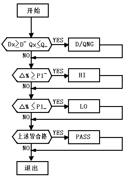
Figure 8-3 1-BIN Sorting Flowchart
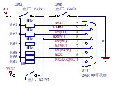
Figure 8-4: Signal Mapping for the Handler Interface (DMR-9P)
The instrument’s operating sequence is shown in Figure 8-5 below:
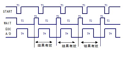
Figure 8-5: Instrument Timing Diagram
T1: The duration of the START signal must be greater than 2.5 ms. The instrument begins measurement when the STARTU signal transitions from high to low; the signal must be removed before T2 returns to low, otherwise another measurement may be triggered unintentionally. If no external START signal is present, pressing the START button on the instrument’s front panel will also generate a start signal.
T2: وقت القياس والحساب للجهاز؛ في نهاية T2، يتم إرسال نتائج الفرز إلى واجهة المعالج.
T3: The waiting time from when WAIT is inactive to when START is active. Determined by the mechanical transmission mechanism.
T4: زمن تحويل الإشارة التناظرية إلى الرقمية للأجهزة.
As shown in Figure 8-5, the valid measurement interval for the output of each component’s measurement and sorting results is the period from the end of the current T2 to the end of the next T2.
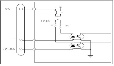
Figure 8-6 Schematic Diagram of Control Signal Inputs (Trigger Signals)
Steps for Comparing and Configuring the HANDLER Interface Limit Lists
Press the [System] key on the instrument to enter the system settings screen. Then, press the “Test Configuration” key on the soft keyboard to enter the test settings screen. Move the cursor to the “Bin Sorting” setting field and select “3 BIN” (three-bin sorting) or “1 BIN” (one-bin sorting). For more information, refer to Section 6.2.6.
Press the instrument’s [Settings] main button to enter the < Measurement Settings> screen, then press the “Limit Settings” soft key to enter the < Limit List Settings> page.
On the < Limit List Settings> page, configure the nominal value, upper limit, and lower limit. For detailed configuration information, refer to Section 5.3, “< Limit List Settings> Page.”
On the < Advanced List Settings> page, move the cursor to the comparison settings field. The soft key display area will show the ON and OFF soft keys. Press the ON soft key to enable the comparison function.
Switch to the < File Number Display> or < File Count Display> screen to perform the measurement.
Finally, configure the HANDLER interface to enable the OUTPUT/INPUT signals.
Special Note: The < File Count Display> also allows you to configure some additional features.
8.3 Methods for Improving Measurement Speed and Efficiency
When using the HANDLER interface to build an automated sorting system, measurement speed and efficiency are critical. With this in mind, users can employ the following two methods to improve test speed and efficiency:
Set the range to the highest inductance value you are likely to measure. For example, if the highest value you might measure is 20 mH, first let the instrument automatically select the range for 20 mH, and then lock the range at that value.
Test it on the < Component Measurement Display> page
إخطار خاص:
The technical specifications and performance metrics in this manual are for reference only; LISUN reserves the right to the final interpretation.
9. LS8517/B Technical Specifications
| اختبار القدرات | اختبار القدرات | LS8517 | LS8517 | LS8517 | LS8517B | LS8517B |
| اختبار القدرات | اختبار القدرات | 100120, 1k, 10k, 40k, 100k (Hz) | 100120, 1k, 10k, 40k, 100k (Hz) | 100120, 1k, 10k, 40k, 100k (Hz) | 50, 60100, 120, 1k, 10k, 40k, 50k, 60k, 100k (Hz) | 50, 60100, 120, 1k, 10k, 40k, 50k, 60k, 100k (Hz) |
| معلمات الاختبار | معلمات الاختبار | C, L, R, D, Q, θ, X, |Z| | C, L, R, D, Q, θ, X, |Z| | C, L, R, D, Q, θ, X, |Z| | C, L, R, D, Q, θ, X, |Z| | C, L, R, D, Q, θ, X, |Z| |
| الدقة الأساسية | الدقة الأساسية | 0.05%; refer to the accuracy table for details | 0.05%; refer to the accuracy table for details | 0.05%; refer to the accuracy table for details | 0.1%; refer to the accuracy table for details | 0.1%; refer to the accuracy table for details |
| اختبار السرعة | اختبار السرعة | Fast: 30 times/second, Medium: 20 times/second, Slow: 6 times/second (frequencies above 1 kHz); Fast: 6 times/second, Medium: 4 times/second, Slow: 2 times/second (frequencies below 1 kHz) | Fast: 30 times/second, Medium: 20 times/second, Slow: 6 times/second (frequencies above 1 kHz); Fast: 6 times/second, Medium: 4 times/second, Slow: 2 times/second (frequencies below 1 kHz) | Fast: 30 times/second, Medium: 20 times/second, Slow: 6 times/second (frequencies above 1 kHz); Fast: 6 times/second, Medium: 4 times/second, Slow: 2 times/second (frequencies below 1 kHz) | Fast: 30 times/second, Medium: 20 times/second, Slow: 6 times/second (frequencies above 1 kHz); Fast: 6 times/second, Medium: 4 times/second, Slow: 2 times/second (frequencies below 1 kHz) | Fast: 30 times per second, Medium: 20 times per second, Slow: 6 times per second (frequencies above 1 kHz); Fast: 6 times per second, Medium: 4 times per second, Slow: 2 times per second (frequencies below 1 kHz) |
| طريقة اختيار النطاق | طريقة اختيار النطاق | تلقائي، تثبيت | تلقائي، تثبيت | تلقائي، تثبيت | طريقة الزناد | داخلي، يدوي، أوتوماتيكي، خارجي، ناقل |
| مستوى الاختبار | مستوى الاختبار | 0.1, 0.3, 1.0 Vrms | 0.1, 0.3, 1.0 Vrms | 0.1, 0.3, 1.0 Vrms | 0.1, 0.3, 1.0 Vrms | 0.1, 0.3, 1.0 Vrms |
| معاوقة مصدر الإشارة | معاوقة مصدر الإشارة | 30 ، 100 | 30 ، 100 | 30 ، 100 | 30 ، 100 | 30 ، 100 |
| وظيفة المعايرة | وظيفة المعايرة | Open Circuit/Short Circuit, Full-Frequency Reset, Spot-Frequency Reset | Open Circuit/Short Circuit, Full-Frequency Reset, Spot-Frequency Reset | Open Circuit/Short Circuit, Full-Frequency Reset, Spot-Frequency Reset | Open Circuit/Short Circuit, Full-Frequency Reset, Spot-Frequency Reset | Open Circuit/Short Circuit, Full-Frequency Reset, Spot-Frequency Reset |
| نطاق العرض | | Z | | 0.1 mΩ — 99.999 MΩ | 0.1 mΩ — 99.999 MΩ | 0.1 mΩ — 99.999 MΩ | 0.1 mΩ — 99.999 MΩ | 0.1 mΩ — 99.999 MΩ |
| نطاق العرض | L | 0.0001 uH–9999.9 H | 0.0001 uH–9999.9 H | 0.0001 uH–9999.9 H | 0.0001 uH–9999.9 H | 0.0001 uH–9999.9 H |
| نطاق العرض | C | 0.0001 pF–9.9999 F | 0.0001 pF–9.9999 F | 0.0001 pF–9.9999 F | 0.0001 pF–9.9999 F | 0.0001 pF–9.9999 F |
| نطاق العرض | R | 0.1 مΩ – 99.999 مΩ | 0.1 مΩ – 99.999 مΩ | 0.1 مΩ – 99.999 مΩ | 0.1 مΩ – 99.999 مΩ | 0.1 مΩ – 99.999 مΩ |
| نطاق العرض | D | 0.0001-9.9999 | 0.0001-9.9999 | 0.0001-9.9999 | 0.0001-9.9999 | 0.0001-9.9999 |
| نطاق العرض | Q | 0.1-9999.9 | 0.1-9999.9 | 0.1-9999.9 | 0.1-9999.9 | 0.1-9999.9 |
| نطاق العرض | Θ(RAD) | -3.1415-3.1415 | -3.1415-3.1415 | -3.1415-3.1415 | -3.1415-3.1415 | -3.1415-3.1415 |
| نطاق العرض | Θ(DEG) | -179.99° -179.99° | -179.99° -179.99° | -179.99 درجة - 179.99 درجة | -179.99° -179.99° | -179.99° -179.99° |
| نطاق العرض | Δ٪ | -99.99%–99.99% | -99.99%–99.99% | -99.99%–99.99% | -99.99%–99.99% | -99.99%–99.99% |
| دائرة مكافئة | دائرة مكافئة | دائرة مكافئة | سلسلة، موازية | سلسلة، موازية | سلسلة، موازية | سلسلة، موازية |
| المقارنة | المقارنة | المقارنة | Four-bin sorting: BIN0–BIN3, NG, AUX | Four-bin sorting: BIN0–BIN3, NG, AUX | Four-bin sorting: BIN0–BIN3, NG, AUX | Four-bin sorting: BIN0–BIN3, NG, AUX |
| المقارنة | المقارنة | المقارنة | ناجح، مرتفع، منخفض (شاشة عرض LED للنجاح/الفشل) | ناجح، مرتفع، منخفض (شاشة عرض LED للنجاح/الفشل) | ناجح، مرتفع، منخفض (مؤشر LED للنجاح/الفشل) | ناجح، مرتفع، منخفض (شاشة عرض LED للنجاح/الفشل) |
| السطح البيني | السطح البيني | السطح البيني | RS232C, USB Host, USB TMC, USB CDC, Handler, GPIB (optional) | RS232C, USB Host, USB TMC, USB CDC, Handler, GPIB (optional) | RS232C, USB Host, USB TMC, USB CDC, Handler, GPIB (optional) | RS232C, USB Host, USB TMC, USB CDC, Handler, GPIB (optional) |
| ذاكرة | ذاكرة | ذاكرة | 50 sets of internal files and 500 sets of files on an external USB drive | 50 sets of internal files and 500 sets of files on an external USB drive | 50 sets of internal files and 500 sets of files on an external USB drive | 50 sets of internal files and 500 sets of external USB drive files |
| درجة الحرارة والرطوبة | درجة الحرارة والرطوبة | درجة الحرارة والرطوبة | 0°C to 40°C, relative humidity ≤ 75% | 0°C to 40°C, relative humidity ≤ 75% | 0°C to 40°C, relative humidity ≤ 75% | 0°C to 40°C, relative humidity ≤ 75% |
| متطلبات الطاقة | متطلبات الطاقة | متطلبات الطاقة | 100–120 VAC or 198–242 VAC, 46–64 Hz, power greater than 50 VA | 100–120 VAC or 198–242 VAC, 46–64 Hz, power greater than 50 VA | 100–120 VAC or 198–242 VAC, 46–64 Hz, power greater than 50 VA | 100–120 VAC or 198–242 VAC, 46–64 Hz, power greater than 50 VA |
| Dimensions (W x H x D) and Weight | Dimensions (W x H x D) and Weight | Dimensions (W x H x D) and Weight | 216 mm × 87 mm × 300 mm, 3.0 kg (net weight) | 216 mm × 87 mm × 300 mm, 3.0 kg (net weight) | 216 mm × 87 mm × 300 mm, 3.0 kg (net weight) | 216 mm × 87 mm × 300 mm, 3.0 kg (net weight) |
| Test accuracy of up to 0.05%, with a fast measurement speed (30 times per second) | Test accuracy of up to 0.05%, with a fast measurement speed (30 times per second) | Test accuracy of up to 0.05%, with a fast measurement speed (30 times per second) | Test accuracy of up to 0.05%, with a fast measurement speed (30 times per second) | 30 Ω, 100 Ω output impedance | 30 Ω, 100 Ω output impedance | 30 Ω, 100 Ω output impedance |
| “Pass” and “Fail” LED indicators, different audio alerts, and different color alerts | “Pass” and “Fail” LED indicators, different audio alerts, and different color indicators | “Pass” and “Fail” LED indicators, different audio alerts, and different color indicators | “Pass” and “Fail” LED indicators, different audio alerts, and different color indicators | The test page allows you to quickly open the circuit, short-circuit it, and reset it, eliminating the need for cumbersome operations. | The test page allows you to quickly perform open-circuit, short-circuit, and reset functions, eliminating the need for cumbersome procedures. | The test page allows you to quickly perform open-circuit, short-circuit, and zero-reset functions, eliminating the need for cumbersome operations. |
| Supports USB flash drive updates, allowing you to quickly save test results and conditions to a USB flash drive | Supports USB flash drive updates, allowing you to quickly save test results and conditions to a USB flash drive | Supports USB flash drive updates, allowing you to quickly save test results and conditions to a USB flash drive | Supports USB flash drive updates, allowing you to quickly save test results and conditions to a USB flash drive | Simple and easy-to-understand SCPI communication protocol that allows for quick setup of a test system with devices | Simple and easy-to-understand SCPI communication protocol that allows for quick setup of a test system with devices | Simple and easy-to-understand SCPI communication protocol that allows for quick setup of test systems with devices |
| Keyboard lock feature; test conditions are automatically saved when the device is turned off, so you don’t need to reset them next time. | Keyboard lock feature; test conditions are automatically saved when the device is turned off, so you don’t need to reset them next time | Keyboard lock feature; test conditions are automatically saved when the device is turned off, so there’s no need to reset them next time | Keyboard lock feature; test conditions are automatically saved when the device is turned off, so you don’t need to reset them next time | Available in Simplified Chinese and English, with a choice of display styles | Available in Simplified Chinese and English, with a choice of different display styles | Available in Simplified Chinese and English, with a choice of different display styles |
| Extensive interface options: RS232, USB-TMC, USB-CDC, Handler, GPIB (optional) | Extensive interface options: RS232, USBTMC, USBCDC, Handler, GPIB (optional) | Extensive interface options: RS232, USBTMC, USBCDC, Handler, GPIB (optional) | Extensive interface options: RS232, USBTMC, USBCDC, Handler, GPIB (optional) | Flexible interface capabilities that allow you to define and implement data recording, storage, and processing according to your needs | Flexible interface capabilities that allow you to define and implement data recording, storage, and processing according to your needs | Flexible interface capabilities that allow you to define and implement data recording, storage, and processing according to your needs |
| Customizable Continuous Levels | Customizable Continuous Levels | Customizable Continuous Levels | Customizable Continuous Levels | You can select either the rising or falling edge (↑ or ↓) for triggering within the instrument. | You can select either the rising or falling edge (↑ or ↓) for triggering within the instrument. | You can select either the rising or falling edge (↑ or ↓) for triggering within the instrument. |
| The instrument’s rear panel features a BNC trigger connector, allowing for quick connection of an external foot switch. | The instrument’s rear panel features a BNC trigger connector, allowing for quick connection of an external foot switch. | The instrument’s rear panel features a BNC trigger connector, allowing for quick connection of an external footswitch. | The instrument’s rear panel features a BNC trigger connector, allowing for quick connection of an external foot switch. | High comparability with LCR bridge data from international brands (Agilent, WK) | High comparability with data from international brand LCR bridges (Agilent, WK) | High comparability with data from international brand manufacturers’ LCR bridges (Agilent, WK) |
Special Note: For the performance specifications of the LS2817/B, please refer to the LS8517/B.
10. LS8510B/C Technical Specifications
| اختبار القدرات | اختبار القدرات | LS8510B | LS8510B | LS8510B | LS8510C | LS8510C |
| اختبار القدرات | اختبار القدرات | 50, 60100, 120, 1k, 10k (Hz) | 50, 60100, 120, 1k, 10k (Hz) | 50, 60100, 120, 1k, 10k (Hz) | 50, 60100, 120, 1k, 10k (Hz) | 50, 60100, 120, 1k, 10k (Hz) |
| معلمات الاختبار | معلمات الاختبار | C, L, R, |Z|, X, G, Q, θ, |Y| | C, L, R, |Z|, X, G, Q, θ, |Y| | C, L, R, |Z|, X, G, Q, θ, |Y| | C, L, R, |Z|, X, G, Q, θ, |Y| | C, L, R, |Z|, X, G, Q, θ, |Y| |
| الدقة الأساسية | الدقة الأساسية | 0.1%; refer to the accuracy table for details | 0.1%; refer to the accuracy table for details | 0.1%; refer to the accuracy table for details | 0.1%; refer to the accuracy table for details | 0.1%; refer to the accuracy table for details |
| اختبار السرعة | اختبار السرعة | Fast: 20 times per second, Medium: 10 times per second, Slow: 6 times per second (frequencies above 1 kHz) | Fast: 20 times per second, Medium: 10 times per second, Slow: 6 times per second (frequencies above 1 kHz) | Fast: 20 times per second, Medium: 10 times per second, Slow: 6 times per second (frequencies above 1 kHz) | Fast: 20 times per second, Medium: 10 times per second, Slow: 6 times per second (frequencies above 1 kHz) | Fast: 20 times per second, Medium: 10 times per second, Slow: 6 times per second (frequencies above 1 kHz) |
| طريقة اختيار النطاق | طريقة اختيار النطاق | تلقائي، تثبيت | تلقائي، تثبيت | تلقائي، تثبيت | طريقة الزناد | داخلي، يدوي، أوتوماتيكي، خارجي، ناقل |
| مستوى الاختبار | مستوى الاختبار | 0.1, 0.3, 1.0 Vrms | 0.1, 0.3, 1.0 Vrms | 0.1, 0.3, 1.0 Vrms | 0.1–1.0 فولت RMS | 0.1–1.0 فولت RMS |
| معاوقة مصدر الإشارة | معاوقة مصدر الإشارة | 30 ، 100 | 30 ، 100 | 30 ، 100 | 30 ، 100 | 30Ω ، 100Ω |
| وظيفة المعايرة | وظيفة المعايرة | Open Circuit/Short Circuit, Full-Frequency Reset, Single-Frequency Reset | Open Circuit/Short Circuit, Full-Frequency Reset, Spot-Frequency Reset | Open Circuit/Short Circuit, Full-Frequency Reset, Single-Frequency Reset | Open Circuit/Short Circuit, Full-Frequency Reset, Spot-Frequency Reset | Open Circuit/Short Circuit, Full-Frequency Reset, Spot-Frequency Reset |
| نطاق العرض | |Z|، R، X | 0.1 mΩ — 99.999 MΩ | 0.1 mΩ — 99.999 MΩ | 0.1 mΩ — 99.999 MΩ | 0.1 mΩ — 99.999 MΩ | 0.1 mΩ — 99.999 MΩ |
| نطاق العرض | L | 0.0001 uH–9999.9 H | 0.0001 uH–9999.9 H | 0.0001 uH–9999.9 H | 0.0001 uH–9999.9 H | 0.0001 uH–9999.9 H |
| نطاق العرض | C | 0.0001 pF–9.9999 F | 0.0001 pF–9.9999 F | 0.0001 pF–9.9999 F | 0.0001 pF–9.9999 F | 0.0001 pF–9.9999 F |
| نطاق العرض | D | 0.0001-9.9999 | 0.0001-9.9999 | 0.0001-9.9999 | 0.0001-9.9999 | 0.0001-9.9999 |
| نطاق العرض | Q | 0.1-9999.9 | 0.1-9999.9 | 0.1-9999.9 | 0.1-9999.9 | 0.1-9999.9 |
| نطاق العرض | Θ(RAD) | -3.1415-3.1415 | -3.1415-3.1415 | -3.1415-3.1415 | -3.1415-3.1415 | -3.1415-3.1415 |
| نطاق العرض | Θ(DEG) | -179.99° -179.99° | -179.99 درجة - 179.99 درجة | -179.99° -179.99° | -179.99° -179.99° | -179.99° -179.99° |
| نطاق العرض | Δ٪ | -99.99%–99.99% | -99.99%–99.99% | -99.99%–99.99% | -99.99%–99.99% | -99.99%–99.99% |
| دائرة مكافئة | دائرة مكافئة | دائرة مكافئة | سلسلة، موازية | سلسلة، موازية | سلسلة، موازية | سلسلة، موازية |
| المقارنة | المقارنة | المقارنة | Four-bin sorting: BIN0–BIN3, NG, AUX | Four-bin sorting: BIN0–BIN3, NG, AUX | Four-bin sorting: BIN0–BIN3, NG, AUX | Four-bin sorting: BIN0–BIN3, NG, AUX |
| المقارنة | المقارنة | المقارنة | ناجح، مرتفع، منخفض (شاشة عرض LED للنجاح/الفشل) | ناجح، مرتفع، منخفض (شاشة عرض LED للنجاح/الفشل) | ناجح، مرتفع، منخفض (شاشة عرض LED للنجاح/الفشل) | ناجح، مرتفع، منخفض (شاشة عرض LED للنجاح/الفشل) |
| السطح البيني | السطح البيني | السطح البيني | RS232C, USB Host, USB TMC, USB CDC, Handler, GPIB (optional) | RS232C, USB Host, USB TMC, USB CDC, Handler, GPIB (optional) | RS232C, USB Host, USB TMC, USB CDC, Handler, GPIB (optional) | RS232C, USB Host, USB TMC, USB CDC, Handler, GPIB (optional) |
| ذاكرة | ذاكرة | ذاكرة | 50 sets of internal files and 500 sets of files on an external USB drive | 50 sets of internal files and 500 sets of files on an external USB drive | 50 sets of files internally, 500 sets on an external USB drive | 50 sets of internal files and 500 sets of files on an external USB drive |
| درجة الحرارة والرطوبة | درجة الحرارة والرطوبة | درجة الحرارة والرطوبة | 0°C to 40°C, relative humidity ≤ 75% | 0°C to 40°C, relative humidity ≤ 75% | 0°C to 40°C, relative humidity ≤ 75% | 0°C to 40°C, relative humidity ≤ 75% |
| متطلبات الطاقة | متطلبات الطاقة | متطلبات الطاقة | 100–120 VAC or 198–242 VAC, 46–64 Hz, power greater than 50 VA | 100–120 VAC or 198–242 VAC, 46–64 Hz, power greater than 50 VA | 100–120 VAC or 198–242 VAC, 46–64 Hz, power greater than 50 VA | 100–120 VAC or 198–242 VAC, 46–64 Hz, power greater than 50 VA |
| Dimensions (W x H x D) and Weight | Dimensions (W x H x D) and Weight | Dimensions (W x H x D) and Weight | 216 mm × 87 mm × 300 mm, 3.0 kg (net weight) | 216 mm × 87 mm × 300 mm, 3.0 kg (net weight) | 216 mm × 87 mm × 300 mm, 3.0 kg (net weight) | 216 mm × 87 mm × 300 mm, 3.0 kg (net weight) |
| Test accuracy of up to 0.1%, with a fast measurement speed (20 times per second) | Test accuracy of up to 0.1%, with fast measurement speed (20 times per second) | Test accuracy of up to 0.1%, with fast measurement speed (20 times per second) | Test accuracy as high as 0.1%, with a fast measurement speed (20 times per second) | 30 Ω, 100 Ω output impedance | 30 Ω, 100 Ω output impedance | 30 Ω, 100 Ω output impedance |
| “Pass” and “Fail” LED indicators, different audio alerts, and different color alerts | “Pass” and “Fail” LED indicators, different audio alerts, and different color indicators | “Pass” and “Fail” LED indicators, different audio alerts, and different color indicators | “Pass” and “Fail” LED indicators, different audio alerts, and different color indicators | The test page allows you to quickly open the circuit, short-circuit it, and reset the device, eliminating the need for cumbersome operations. | The test page allows you to quickly perform open-circuit, short-circuit, and reset functions, eliminating the need for cumbersome procedures. | The test page allows you to quickly perform open-circuit, short-circuit, and reset functions, eliminating the need for cumbersome operations. |
| Supports USB flash drive updates, allowing you to quickly save test results and conditions to a USB flash drive | Supports USB flash drive updates, allowing you to quickly save test results and conditions to a USB flash drive | Supports USB flash drive updates, allowing test results and conditions to be quickly saved to a USB flash drive | Supports USB flash drive updates, allowing you to quickly save test results and conditions to a USB flash drive | Simple and easy-to-understand SCPI communication protocol that allows for quick setup of a test system with devices | Simple and easy-to-understand SCPI communication protocol that allows for quick setup of a test system with devices | Simple and easy-to-understand SCPI communication protocol that allows for quick setup of a test system with devices |
| Test conditions are automatically saved when the device is turned off, so there’s no need to reset them next time. | Test conditions are automatically saved when the device is turned off, so there’s no need to reset them next time. | Test conditions are automatically saved when the system is shut down, so there is no need to reconfigure them next time. | Test conditions are automatically saved when the device is turned off, so there is no need to reconfigure them next time. | Available in Simplified Chinese and English, with a choice of different display styles | Available in Simplified Chinese and English, with a choice of different display styles | Available in Simplified Chinese and English; offers a choice of display styles |
| Extensive interface options: RS232, USBTMC, USBCDC, Handler, GPIB (optional) | Extensive interface options: RS232, USBTMC, USBCDC, Handler, GPIB (optional) | Extensive interface options: RS232, USBTMC, USBCDC, Handler, GPIB (optional) | Extensive interface options: RS232, USBTMC, USBCDC, Handler, GPIB (optional) | Flexible interface capabilities that allow you to define and implement data recording, storage, and processing according to your needs | Flexible interface capabilities that allow you to define and implement data recording, storage, and processing according to your needs. | Flexible interface capabilities that allow you to define and implement data recording, storage, and processing according to your needs |
| Highly stable capacitive loss ensures reliable performance of capacitors right out of the factory | Highly stable capacitive loss ensures reliable quality control for capacitors at the factory | Highly stable capacitance loss ensures reliable performance of capacitors right out of the factory | Highly stable capacitance loss ensures reliable performance for capacitors right out of the factory | You can select either the rising or falling edge (↑ or ↓) for triggering within the instrument. | You can select either the rising or falling edge (↑ or ↓) for triggering within the instrument. | You can select either the rising or falling edge (↑ or ↓) for triggering within the instrument. |
| The instrument’s rear panel features a BNC trigger connector, allowing for quick connection of an external foot switch. | The instrument’s rear panel features a BNC trigger connector, allowing for quick connection of an external foot switch. | The instrument’s rear panel features a BNC trigger connector, allowing for quick connection of an external foot switch. | The instrument’s rear panel features a BNC trigger connector, allowing for quick connection of an external foot switch. | High comparability with data from international brand manufacturers’ LCR bridges (Agilent, WK) | High comparability with data from international brand manufacturers’ LCR bridges (Agilent, WK) | High comparability with data from international brand manufacturers’ LCR bridges (Agilent, WK) |
Special Note: For the performance specifications of the LS2810B/C, please refer to the LS8510B/C.
11. LS8511C/D Technical Specifications
| اختبار القدرات | اختبار القدرات | LS8511C | LS8511C | LS8511C | LS8511D | LS8511D |
| اختبار القدرات | اختبار القدرات | 100, 1k, 10k (Hz) | 100, 1k, 10k (Hz) | 100, 1k, 10k (Hz) | 100120, 1k, 10k (Hz) | 100120, 1k, 10k (Hz) |
| معلمات الاختبار | معلمات الاختبار | C, L, R, |Z|, D, Q | C, L, R, |Z|, D, Q | C, L, R, |Z|, D, Q | C, L, R, |Z|, D, Q | C, L, R, |Z|, D, Q |
| الدقة الأساسية | الدقة الأساسية | 0.25%; refer to the accuracy table for details | 0.25%; refer to the accuracy table for details | 0.25%; refer to the accuracy table for details | 0.2%; refer to the accuracy table for details | 0.2%; refer to the accuracy table for details |
| اختبار السرعة | اختبار السرعة | Fast: 15 times/second, Medium: 10 times/second, Slow: 6 times/second (frequencies above 1 kHz); Fast: 6 times/second, Medium: 4 times/second, Slow: 2 times/second (frequencies below 1 kHz) | Fast: 15 times/second, Medium: 10 times/second, Slow: 6 times/second (frequencies above 1 kHz); Fast: 6 times/second, Medium: 4 times/second, Slow: 2 times/second (frequencies below 1 kHz) | Fast: 15 times/second, Medium: 10 times/second, Slow: 6 times/second (frequencies above 1 kHz); Fast: 6 times/second, Medium: 4 times/second, Slow: 2 times/second (frequencies below 1 kHz) | Fast: 15 times/second, Medium: 10 times/second, Slow: 6 times/second (frequencies above 1 kHz); Fast: 6 times/second, Medium: 4 times/second, Slow: 2 times/second (frequencies below 1 kHz) | Fast: 15 times/second, Medium: 10 times/second, Slow: 6 times/second (frequencies above 1 kHz); Fast: 6 times/second, Medium: 4 times/second, Slow: 2 times/second (frequencies below 1 kHz) |
| طريقة اختيار النطاق | طريقة اختيار النطاق | تلقائي، تثبيت | تلقائي، تثبيت | تلقائي، تثبيت | طريقة الزناد | Internal, Manual |
| مستوى الاختبار | مستوى الاختبار | 0.1, 0.3, 1.0 Vrms | 0.1, 0.3, 1.0 Vrms | 0.1, 0.3, 1.0 Vrms | 0.1, 0.3, 1.0 Vrms | 0.1, 0.3, 1.0 Vrms |
| معاوقة مصدر الإشارة | معاوقة مصدر الإشارة | 30 ، 100 | 30 ، 100 | 30 ، 100 | 30 ، 100 | 30 ، 100 |
| وظيفة المعايرة | وظيفة المعايرة | Open Circuit/Short Circuit, Full-Frequency Reset, Spot-Frequency Reset | Open Circuit/Short Circuit, Full-Frequency Reset, Spot-Frequency Reset | Open Circuit/Short Circuit, Full-Frequency Reset, Single-Frequency Reset | Open Circuit/Short Circuit, Full-Frequency Reset, Spot-Frequency Reset | Open Circuit/Short Circuit, Full-Frequency Reset, Single-Frequency Reset |
| نطاق العرض | |Z|, R | 0.1 mΩ — 99.999 MΩ | 0.1 mΩ — 99.999 MΩ | 0.1 mΩ — 99.999 MΩ | 0.1 mΩ — 99.999 MΩ | 0.1 mΩ — 99.999 MΩ |
| نطاق العرض | L | 0.0001 uH–9999.9 H | 0.0001 uH–9999.9 H | 0.0001 uH–9999.9 H | 0.0001 uH–9999.9 H | 0.0001 uH–9999.9 H |
| نطاق العرض | C | 0.0001 pF–9.9999 F | 0.0001 pF–9.9999 F | 0.0001 pF–9.9999 F | 0.0001 pF–9.9999 F | 0.0001 pF–9.9999 F |
| نطاق العرض | D | 0.0001-9.9999 | 0.0001-9.9999 | 0.0001-9.9999 | 0.0001-9.9999 | 0.0001-9.9999 |
| نطاق العرض | Q | 0.1-9999.9 | 0.1-9999.9 | 0.1-9999.9 | 0.1-9999.9 | 0.1-9999.9 |
| دائرة مكافئة | دائرة مكافئة | دائرة مكافئة | Series, Parallel, Automatic | Series, Parallel, Automatic | Series, Parallel, Automatic | Series, Parallel, Automatic |
| المقارنة | المقارنة | المقارنة | مزيد من الخيارات | مزيد من الخيارات | مزيد من الخيارات | مزيد من الخيارات |
| السطح البيني | السطح البيني | السطح البيني | RS232C (optional), USB Host, USB TMC (optional), USB CDC (optional), Handler (optional) | RS232C (optional), USB Host, USB TMC (optional), USB CDC (optional), Handler (optional) | RS232C (optional), USB Host, USB TMC (optional), USB CDC (optional), Handler (optional) | RS232C (optional), USB Host, USB TMC (optional), USB CDC (optional), Handler (optional) |
| ذاكرة | ذاكرة | ذاكرة | 50 sets of internal files and 500 sets of files on an external USB drive | 50 sets of internal files and 500 sets of files on an external USB drive | 50 sets of files internally, and 500 sets on an external USB drive | 50 sets of internal files and 500 sets of files on an external USB drive |
| درجة الحرارة والرطوبة | درجة الحرارة والرطوبة | درجة الحرارة والرطوبة | 0°C to 40°C, relative humidity ≤ 75% | 0°C to 40°C, relative humidity ≤ 75% | 0°C to 40°C, relative humidity ≤ 75% | 0°C to 40°C, relative humidity ≤ 75% |
| متطلبات الطاقة | متطلبات الطاقة | متطلبات الطاقة | 100–120 VAC or 198–242 VAC, 46–64 Hz, power greater than 50 VA | 100–120 VAC or 198–242 VAC, 46–64 Hz, power greater than 50 VA | 100–120 VAC or 198–242 VAC, 46–64 Hz, power greater than 50 VA | 100–120 VAC or 198–242 VAC, 46–64 Hz, power greater than 50 VA |
| Dimensions (W x H x D) and Weight | Dimensions (W x H x D) and Weight | Dimensions (W x H x D) and Weight | 216 mm × 87 mm × 300 mm, 3.0 kg (net weight) | 216 mm × 87 mm × 300 mm, 3.0 kg (net weight) | 216 mm × 87 mm × 300 mm, 3.0 kg (net weight) | 216 mm × 87 mm × 300 mm, 3.0 kg (net weight) |
| Highly stable capacitance loss ensures reliable performance of capacitors right out of the factory | Highly stable capacitance loss ensures reliable performance of capacitors right out of the factory | Highly stable capacitance loss ensures reliable performance right out of the box | Highly stable capacitance loss ensures reliable performance right out of the factory | 30 Ω, 100 Ω output impedance | 30 Ω, 100 Ω output impedance | 30 Ω, 100 Ω output impedance |
| “Pass” and “Fail” LED indicators, different audio alerts, and different color indicators | “Pass” and “Fail” LED indicators, different audio alerts, and different color indicators | “Pass” and “Fail” LED indicators, different audio alerts, and different color indicators | “Pass” and “Fail” LED indicators, different audio alerts, and different color indicators | The test page allows you to quickly perform open-circuit, short-circuit, and reset functions, eliminating the need for cumbersome operations. | The test page allows you to quickly perform open-circuit, short-circuit, and reset functions, eliminating the need for cumbersome operations. | The test page allows you to quickly perform open-circuit and short-circuit reset functions, eliminating the need for cumbersome procedures. |
| Supports USB flash drive updates, allowing you to quickly save test results and conditions to a USB flash drive | Supports USB flash drive updates, allowing you to quickly save test results and conditions to a USB flash drive | Supports USB flash drive updates, allowing you to quickly save test results and conditions to a USB flash drive | Supports USB flash drive updates, allowing you to quickly save test results and conditions to a USB flash drive | Simple and easy-to-understand SCPI communication protocol that allows for quick setup of test systems with devices | Simple and easy-to-understand SCPI communication protocol that allows for quick setup of test systems with devices | Simple and easy-to-understand SCPI communication protocol that allows for quick setup of a test system with devices |
| Test conditions are automatically saved when the device is turned off, so there’s no need to reset them next time. | Test conditions are automatically saved when the device is turned off, so there’s no need to reconfigure them next time. | Test conditions are automatically saved when the device is turned off, so you won’t need to reconfigure them next time. | Test conditions are automatically saved when the device is turned off, so there is no need to reconfigure them next time. | Available in Simplified Chinese and English, with a choice of different display styles | Available in Simplified Chinese and English, with a choice of different display styles | Available in Simplified Chinese and English, with a choice of different display styles |
| The instrument’s rear panel features a BNC trigger connector, allowing for quick connection of an external foot switch. | The instrument’s rear panel features a BNC trigger connector, allowing for quick connection of an external footswitch. | The instrument’s rear panel features a BNC trigger connector, allowing for quick connection of an external footswitch. | The instrument’s rear panel features a BNC trigger connector, allowing for quick connection of an external footswitch. | You can select either the rising or falling edge (↑ or ↓) for triggering within the instrument. | You can select either the rising or falling edge (↑ or ↓) for triggering within the instrument. | You can select either the rising or falling edge (↑ or ↓) for triggering within the instrument. |
Special Note: For the performance specifications of the LS2811C/D, please refer to the LS8511C/D.
12. LS6517/LS6517A Technical Specifications
| اختبار القدرات | اختبار القدرات | LS6517 | LS6517 | LS6517 | LS6517A | LS6517A |
| اختبار القدرات | اختبار القدرات | 50, 60100, 120, 1k, 10k, 40k, 50k, 60k, 100k (Hz) | 50, 60100, 120, 1k, 10k, 40k, 50k, 60k, 100k (Hz) | 50, 60100, 120, 1k, 10k, 40k, 50k, 60k, 100k (Hz) | 50, 60100, 120, 1k, 10k, 40k, 50k, 60k, 100k (Hz) | 50, 60100, 120, 1k, 10k, 40k, 50k, 60k, 100k (Hz) |
| معلمات الاختبار | معلمات الاختبار | C, R, Q, θ, X, |Z| | C, R, Q, θ, X, |Z| | C, R, Q, θ, X, |Z| | C, R, Q, X, |Z| | C, R, Q, X, |Z| |
| الدقة الأساسية | الدقة الأساسية | 0.05%; refer to the accuracy table for details | 0.05%; refer to the accuracy table for details | 0.05%; refer to the accuracy table for details | 0.05%; refer to the accuracy table for details | 0.05%; refer to the accuracy table for details |
| اختبار السرعة | اختبار السرعة | Fast: 30 times per second, Medium: 20 times per second, Slow: 6 times per second (frequencies above 1 kHz) | Fast: 30 times per second, Medium: 20 times per second, Slow: 6 times per second (frequencies above 1 kHz) | Fast: 30 times/second, Medium: 20 times/second, Slow: 6 times/second (frequencies above 1 kHz) | Fast: 30 times per second, Medium: 20 times per second, Slow: 6 times per second (frequencies above 1 kHz) | Fast: 30 times per second, Medium: 20 times per second, Slow: 6 times per second (frequencies above 1 kHz) |
| طريقة اختيار النطاق | طريقة اختيار النطاق | تلقائي، تثبيت | تلقائي، تثبيت | تلقائي، تثبيت | طريقة الزناد | داخلي، يدوي، أوتوماتيكي، خارجي، ناقل |
| مستوى الاختبار | مستوى الاختبار | 0.1, 0.3, 1.0 Vrms | 0.1, 0.3, 1.0 Vrms | 0.1, 0.3, 1.0 Vrms | Dual-Frequency Tester (Frequency 1, Frequency 2) | Dual-Frequency Tester (Frequency 1, Frequency 2) |
| معاوقة مصدر الإشارة | معاوقة مصدر الإشارة | 30 ، 100 | 30 ، 100 | 30 ، 100 | 30 ، 100 | 30 ، 100 |
| وظيفة المعايرة | وظيفة المعايرة | Open Circuit/Short Circuit, Full-Frequency Reset, Single-Frequency Reset | Open Circuit/Short Circuit, Full-Frequency Reset, Spot-Frequency Reset | Open Circuit/Short Circuit, Full-Frequency Reset, Single-Frequency Reset | Open Circuit/Short Circuit, Full-Frequency Reset, Single-Frequency Reset | Open Circuit/Short Circuit, Full-Frequency Reset, Spot-Frequency Reset |
| نطاق العرض | |Z|, X | 0.1 mΩ — 99.999 MΩ | 0.1 mΩ — 99.999 MΩ | 0.1 mΩ — 99.999 MΩ | 0.1 mΩ — 99.999 MΩ | 0.1 mΩ — 99.999 MΩ |
| نطاق العرض | C | 0.0001 pF–9.9999 F | 0.0001 pF–9.9999 F | 0.0001 pF–9.9999 F | 0.0001 pF–9.9999 F | 0.0001 pF–9.9999 F |
| نطاق العرض | R | 0.1 مΩ – 99.999 مΩ | 0.1 مΩ – 99.999 مΩ | 0.1 مΩ – 99.999 مΩ | 0.1 مΩ – 99.999 مΩ | 0.1 مΩ – 99.999 مΩ |
| نطاق العرض | D | 0.0001-9.9999 | 0.0001-9.9999 | 0.0001-9.9999 | 0.0001-9.9999 | 0.0001-9.9999 |
| نطاق العرض | Q | 0.1-9999.9 | 0.1-9999.9 | 0.1-9999.9 | 0.1-9999.9 | 0.1-9999.9 |
| نطاق العرض | Θ(RAD) | -3.1415-3.1415 | -3.1415-3.1415 | -3.1415-3.1415 | -3.1415-3.1415 | -3.1415-3.1415 |
| نطاق العرض | Θ(DEG) | -179.99° -179.99° | -179.99° -179.99° | -179.99° -179.99° | -179.99° -179.99° | -179.99° -179.99° |
| نطاق العرض | Δ٪ | -99.99%–99.99% | -99.99%–99.99% | -99.99% – 99.99% | -99.99%–99.99% | -99.99%–99.99% |
| دائرة مكافئة | دائرة مكافئة | دائرة مكافئة | سلسلة، موازية | سلسلة، موازية | سلسلة، موازية | سلسلة، موازية |
| المقارنة | المقارنة | المقارنة | Four-bin sorting: BIN0–BIN3, NG, AUX | Four-bin sorting: BIN0–BIN3, NG, AUX | Four-bin sorting: BIN0–BIN3, NG, AUX | Four-bin sorting: BIN0–BIN3, NG, AUX |
| المقارنة | المقارنة | المقارنة | ناجح، مرتفع، منخفض (شاشة عرض LED للنجاح/الفشل) | ناجح، مرتفع، منخفض (شاشة عرض LED للنجاح/الفشل) | ناجح، مرتفع، منخفض (شاشة عرض LED للنجاح/الفشل) | ناجح، مرتفع، منخفض (شاشة عرض LED للنجاح/الفشل) |
| السطح البيني | السطح البيني | السطح البيني | RS232C, USB Host, USB TMC, USB CDC, Handler, GPIB (optional) | RS232C, USB Host, USB TMC, USB CDC, Handler, GPIB (optional) | RS232C, USB Host, USB TMC, USB CDC, Handler, GPIB (optional) | RS232C, USB Host, USB TMC, USB CDC, Handler, GPIB (optional) |
| ذاكرة | ذاكرة | ذاكرة | 50 sets of internal files and 500 sets of files on an external USB drive | 50 sets of files on the internal drive and 500 sets on an external USB drive | 50 sets of internal files and 500 sets of files on an external USB drive | 50 sets of internal files and 500 sets of files on an external USB drive |
| درجة الحرارة والرطوبة | درجة الحرارة والرطوبة | درجة الحرارة والرطوبة | 0°C to 40°C, relative humidity ≤ 75% | 0°C to 40°C, relative humidity ≤ 75% | 0°C to 40°C, relative humidity ≤ 75% | 0°C to 40°C, relative humidity ≤ 75% |
| متطلبات الطاقة | متطلبات الطاقة | متطلبات الطاقة | 100–120 VAC or 198–242 VAC, 46–64 Hz, power greater than 50 VA | 100–120 VAC or 198–242 VAC, 46–64 Hz, power greater than 50 VA | 100–120 VAC or 198–242 VAC, 46–64 Hz, power greater than 50 VA | 100–120 VAC or 198–242 VAC, 46–64 Hz, power greater than 50 VA |
| Dimensions (W x H x D) and Weight | Dimensions (W x H x D) and Weight | Dimensions (W x H x D) and Weight | 216 mm × 87 mm × 300 mm, 3.0 kg (net weight) | 216 mm × 87 mm × 300 mm, 3.0 kg (net weight) | 216 mm × 87 mm × 300 mm, 3.0 kg (net weight) | 216 mm × 87 mm × 300 mm, 3.0 kg (net weight) |
| LS2617A Customizable Dual-Band Functionality | LS2617A Customizable Dual-Band Functionality | LS2617A Customizable Dual-Band Functionality | LS2617A Customizable Dual-Band Functionality | 30Ω, 100Ω output impedance | 30 Ω, 100 Ω output impedance | 30Ω, 100Ω output impedance |
| Test accuracy of up to 0.05% and fast measurement speed (30 times per second) | Test accuracy of up to 0.05%, with a fast measurement speed (30 times per second) | Test accuracy as high as 0.05%, with fast measurement speed (30 times per second) | Test accuracy of up to 0.05%, with a fast measurement speed (30 times per second) | The test page allows you to quickly perform open-circuit, short-circuit, and reset functions, eliminating the need for cumbersome operations. | The test page allows you to quickly perform open-circuit, short-circuit, and reset functions, eliminating the need for cumbersome operations. | The test page allows you to quickly perform open-circuit, short-circuit, and reset functions, eliminating the need for cumbersome operations. |
| “Pass” and “Fail” LED indicators, different audio alerts, and different color indicators | “Pass” and “Fail” LED indicators, different audio alerts, and different color indicators | “Pass” and “Fail” LED indicators, different audio alerts, and different color indicators | “Pass” and “Fail” LED indicators, different audio alerts, and different color indicators | Simple and easy-to-understand SCPI communication protocol that allows for quick setup of a test system with devices | Simple and easy-to-understand SCPI communication protocol that allows for quick setup of a test system with devices | Simple and easy-to-understand SCPI communication protocol that allows for quick setup of a test system with devices |
| Supports USB flash drive updates, allowing you to quickly save test results and conditions to a USB flash drive | Supports USB flash drive upgrades, allowing you to quickly save test results and conditions to a USB flash drive | Supports USB flash drive upgrades, allowing you to quickly save test results and conditions to a USB flash drive | Supports USB flash drive upgrades, allowing test results and conditions to be quickly saved to a USB flash drive | Available in Simplified Chinese and English; offers a choice of different display styles | Available in Simplified Chinese and English, with a choice of different display styles | Available in Simplified Chinese and English, with a choice of different display styles |
| Keyboard lock feature; test conditions are automatically saved when the device is turned off, so there’s no need to reset them next time | Keyboard lock feature; test conditions are automatically saved when the device is turned off, so there’s no need to reset them next time | Keyboard lock feature; test conditions are automatically saved when the device is turned off, so there’s no need to reset them next time. | Keyboard lock feature; test conditions are automatically saved when the device is turned off, so there’s no need to reset them next time | Flexible interface capabilities that allow you to define and implement data recording, storage, and processing according to your needs | Flexible interface capabilities that allow you to define and implement data recording, storage, and processing according to your needs | Flexible interface functionality that allows you to define and implement data recording, storage, and processing according to your needs |
| Extensive interface options: RS232, USBTMC, USBCDC, Handler, GPIB (optional) | Extensive interface options: RS232, USBTMC, USBCDC, Handler, GPIB (optional) | Extensive interface options: RS232, USBTMC, USBCDC, Handler, GPIB (optional) | Extensive interface options: RS232, USBTMC, USBCDC, Handler, GPIB (optional) | You can select either the rising or falling edge (↑ or ↓) for triggering within the instrument. | You can select either the rising or falling edge (↑ or ↓) inside the instrument for triggering. | You can select either the rising or falling edge (↑ or ↓) for triggering within the instrument. |
| The instrument’s rear panel features a BNC trigger connector, allowing for quick connection of an external foot switch. | The instrument’s rear panel features a BNC trigger connector, allowing for quick connection of an external footswitch. | The instrument’s rear panel features a BNC trigger connector, allowing for quick connection of an external foot switch. | The rear panel of the instrument features a BNC trigger connector, allowing for quick connection of an external foot switch. | High comparability with data from international brand manufacturers’ LCR bridges (Agilent, WK) | High comparability with data from international brand manufacturers’ LCR bridges (Agilent, WK) | High comparability with data from international brand manufacturers’ LCR bridges (Agilent, WK) |
Special Note: For the performance specifications of the LS2617/A, please refer to the LS6517/A.
13. LS6518B/LS6515F Technical Specifications
| اختبار القدرات | اختبار القدرات | LS6518B | LS6518B | LS6518B | LS6515F | LS6515F |
| اختبار القدرات | اختبار القدرات | 100120, 1k, 10k | 100120, 1k, 10k | 100120, 1k, 10k | 100120 | 100120 |
| معلمات الاختبار | معلمات الاختبار | C, R, D, |Z|, X | C, R, D, |Z|, X | C, R, D, |Z|, X | C, R, D, |Z| | C, R, D, |Z| |
| الدقة الأساسية | الدقة الأساسية | 0.1%; refer to the accuracy table for details | 0.1%; refer to the accuracy table for details | 0.1%; refer to the accuracy table for details | 0.25%; refer to the accuracy table for details | 0.25%; refer to the accuracy table for details |
| اختبار السرعة | اختبار السرعة | Fast: 30 times/second, Medium: 20 times/second, Slow: 6 times/second (LS6518B) Fast: 10 times/second, Medium: 5 times/second, Slow: 1.5 times/second (LS6515F) | Fast: 30 times/second, Medium: 20 times/second, Slow: 6 times/second (LS6518B) Fast: 10 times/second, Medium: 5 times/second, Slow: 1.5 times/second (LS6515F) | Fast: 30 times/second, Medium: 20 times/second, Slow: 6 times/second (LS6518B) Fast: 10 times/second, Medium: 5 times/second, Slow: 1.5 times/second (LS6515F) | Fast: 30 times/second, Medium: 20 times/second, Slow: 6 times/second (LS6518B) Fast: 10 times/second, Medium: 5 times/second, Slow: 1.5 times/second (LS6515F) | Fast: 30 times/second, Medium: 20 times/second, Slow: 6 times/second (LS6518B) Fast: 10 times/second, Medium: 5 times/second, Slow: 1.5 times/second (LS6515F) |
| طريقة اختيار النطاق | طريقة اختيار النطاق | تلقائي، تثبيت | تلقائي، تثبيت | تلقائي، تثبيت | طريقة الزناد | داخلي، يدوي، أوتوماتيكي، خارجي، ناقل |
| مستوى الاختبار | مستوى الاختبار | 0.1, 0.3, 1.0 Vrms | 0.1, 0.3, 1.0 Vrms | 0.1, 0.3, 1.0 Vrms | 1.0 فرمات | 1.0 فرمات |
| معاوقة مصدر الإشارة | معاوقة مصدر الإشارة | 30 ، 100 | 30 ، 100 | 30 ، 100 | 3Ω | 3Ω |
| وظيفة المعايرة | وظيفة المعايرة | Open Circuit/Short Circuit, Full-Frequency Reset, Single-Frequency Reset | Open Circuit/Short Circuit, Full-Frequency Reset, Spot-Frequency Reset | Open Circuit/Short Circuit, Full-Frequency Reset, Spot-Frequency Reset | Open Circuit/Short Circuit, Full-Frequency Reset, Spot-Frequency Reset | Open Circuit/Short Circuit, Full-Frequency Reset, Spot-Frequency Reset |
| نطاق العرض | |Z|, X | 0.1 mΩ — 99.999 MΩ | 0.1 mΩ — 99.999 MΩ | 0.1 mΩ — 99.999 MΩ | 0.1 mΩ — 99.999 MΩ | 0.1 mΩ — 99.999 MΩ |
| نطاق العرض | C | 0.0001 pF–9.9999 F | 0.0001 pF–9.9999 F | 0.0001 pF–9.9999 F | 0.0001 pF–9.9999 F | 0.0001 pF–9.9999 F |
| نطاق العرض | R | 0.1 مΩ – 99.999 مΩ | 0.1 مΩ – 99.999 مΩ | 0.1 مΩ – 99.999 مΩ | 0.1 مΩ – 99.999 مΩ | 0.1 مΩ – 99.999 مΩ |
| نطاق العرض | D | 0.0001-9.9999 | 0.0001-9.9999 | 0.0001-9.9999 | 0.0001-9.9999 | 0.0001-9.9999 |
| دائرة مكافئة | دائرة مكافئة | دائرة مكافئة | سلسلة، موازية | سلسلة، موازية | سلسلة، موازية | سلسلة، موازية |
| المقارنة | المقارنة | المقارنة | Four-bin sorting: BIN0–BIN3, NG, AUX | Four-bin sorting: BIN0–BIN3, NG, AUX | Four-category sorting: BIN0–BIN3, NG, AUX | Four-bin sorting: BIN0–BIN3, NG, AUX |
| المقارنة | المقارنة | المقارنة | ناجح، مرتفع، منخفض (شاشة عرض LED للنجاح/الفشل) | ناجح، مرتفع، منخفض (شاشة عرض LED للنجاح/الفشل) | ناجح، مرتفع، منخفض (شاشة عرض LED للنجاح/الفشل) | ناجح، مرتفع، منخفض (شاشة عرض LED للنجاح/الفشل) |
| السطح البيني | السطح البيني | السطح البيني | RS232C, USB Host, USB TMC, USB CDC, Handler, GPIB (optional) | RS232C, USB Host, USB TMC, USB CDC, Handler, GPIB (optional) | RS232C, USB Host, USB TMC, USB CDC, Handler, GPIB (optional) | RS232C, USB Host, USB TMC, USB CDC, Handler, GPIB (optional) |
| ذاكرة | ذاكرة | ذاكرة | 50 sets of internal files and 500 sets of files on an external USB drive | 50 sets of internal files and 500 sets of files on an external USB drive | 50 sets of internal files and 500 sets of files on an external USB drive | 50 sets of internal files and 500 sets of files on an external USB drive |
| درجة الحرارة والرطوبة | درجة الحرارة والرطوبة | درجة الحرارة والرطوبة | 0°C to 40°C, relative humidity ≤ 75% | 0°C to 40°C, relative humidity ≤ 75% | 0°C to 40°C, relative humidity ≤ 75% | 0°C to 40°C, relative humidity ≤ 75% |
| متطلبات الطاقة | متطلبات الطاقة | متطلبات الطاقة | 100–120 VAC or 198–242 VAC, 46–64 Hz, power greater than 50 VA | 100–120 VAC or 198–242 VAC, 46–64 Hz, power greater than 50 VA | 100–120 VAC or 198–242 VAC, 46–64 Hz, power greater than 50 VA | 100–120 VAC or 198–242 VAC, 46–64 Hz, power greater than 50 VA |
| Dimensions (W x H x D) and Weight | Dimensions (W x H x D) and Weight | Dimensions (W x H x D) and Weight | 216 mm × 87 mm × 300 mm, 3.0 kg (net weight) | 216 mm × 87 mm × 300 mm, 3.0 kg (net weight) | 216 mm × 87 mm × 300 mm, 3.0 kg (net weight) | 216 mm × 87 mm × 300 mm, 3.0 kg (net weight) |
| “Pass” and “Fail” LED indicators, different audio alerts, and different color indicators | “Pass” and “Fail” LED indicators, different audio alerts, and different color indicators | “Pass” and “Fail” LED indicators, different audio alerts, and different color alerts | “Pass” and “Fail” LED indicators, different audio alerts, and different color alerts | The test page allows you to quickly perform open-circuit, short-circuit, and reset functions, eliminating the need for cumbersome operations. | The test page allows you to quickly perform open-circuit, short-circuit, and reset functions, eliminating the need for cumbersome operations. | The test page allows you to quickly perform open-circuit, short-circuit, and reset functions, eliminating the need for cumbersome operations. |
| Supports USB flash drive updates, allowing you to quickly save test results and conditions to a USB flash drive | Supports USB flash drive updates, allowing you to quickly save test results and conditions to a USB flash drive | Supports USB flash drive updates, allowing test results and settings to be quickly saved to a USB flash drive | Supports USB flash drive updates, allowing you to quickly save test results and conditions to a USB flash drive | Simple and easy-to-understand SCPI communication protocol that allows for quick setup of a test system with devices | Simple and easy-to-understand SCPI communication protocol that allows for quick setup of a test system with devices | Simple and easy-to-understand SCPI communication protocol; allows for quick setup of test systems with devices |
| Test conditions are automatically saved when the device is turned off, so there’s no need to reset them next time. | Test conditions are automatically saved when the device is turned off, so there’s no need to reset them next time. | Test conditions are automatically saved when the device is turned off, so there’s no need to reset them next time. | Test conditions are automatically saved when the device is turned off, so there’s no need to reconfigure them next time. | Available in Simplified Chinese and English; offers a choice of display styles | Available in Simplified Chinese and English, with a choice of different display styles | Available in Simplified Chinese and English, with a choice of different display styles |
| Extensive interface options: RS232, USBTMC, USBCDC, Handler, GPIB (optional) | Extensive interface options: RS232, USBTMC, USBCDC, Handler, GPIB (optional) | Extensive interface options: RS232, USBTMC, USBCDC, Handler, GPIB (optional) | Extensive interface options: RS232, USBTMC, USBCDC, Handler, GPIB (optional) | Flexible interface capabilities that allow you to define and implement data recording, storage, and processing according to your needs | Flexible interface capabilities that allow you to define and implement data recording, storage, and processing according to your needs | Flexible interface capabilities that allow you to define and implement data recording, storage, and processing according to your needs |
| The rear panel of the instrument features a BNC trigger connector, allowing for quick connection to an external foot switch. | The instrument’s rear panel features a BNC trigger connector, allowing for quick connection of an external foot switch. | The instrument’s rear panel features a BNC trigger connector, allowing for quick connection of an external footswitch. | The instrument’s rear panel features a BNC trigger connector, allowing for quick connection of an external foot switch. | You can select either the rising or falling edge (↑ or ↓) for triggering within the instrument. | You can select either the rising or falling edge (↑ or ↓) for triggering within the instrument. | You can select either the rising or falling edge (↑ or ↓) for triggering within the instrument. |
Special Note: For the performance specifications of the LS2618B/LS2615F, please refer to the LS6518B/LS6515F.
14. LS7576/LS7575B/LS7573A/LS7575CX Technical Specifications
| اختبار القدرات | اختبار القدرات | LS7576 | LS7576 | LS7575B/LS7575CX | LS7575B/LS7575CX | LS7575B/LS7575CX | LS7575B/LS7575CX | LS7573A |
| اختبار القدرات | اختبار القدرات | 50, 60100, 120, 1k, 10k, 40k, 50k, 60k, 100k (Hz) | 50, 60100, 120, 1k, 10k, 40k, 50k, 60k, 100k (Hz) | 100120, 1k, 10k, | 100120, 1k, 10k, | 100120, 1k, 10k, | 100120, 1k, 10k, | 100 هرتز، 1 كيلو هرتز |
| معلمات الاختبار | معلمات الاختبار | L, R, Q, |Z| The LS7575CX features an inductance balancing test function | L, R, Q, |Z| The LS7575CX features inductance balance testing | L, R, Q, |Z| The LS7575CX features an inductance balance test function | L, R, Q, |Z| The LS7575CX features inductance balance testing | L, R, Q, |Z| The LS7575CX features an inductance balance test function | L, R, Q, |Z| The LS7575CX features an inductance balance test function | L, R, Q, |Z| The LS7575CX features an inductance balance test function |
| الدقة الأساسية | الدقة الأساسية | 0.05%; refer to the accuracy table for details | 0.05%; refer to the accuracy table for details | 0.1%; refer to the accuracy table for details | 0.1%; refer to the accuracy table for details | 0.1%; refer to the accuracy table for details | 0.1%; refer to the accuracy table for details | 0.1%; refer to the accuracy table for details |
| اختبار السرعة | اختبار السرعة | Fast: 30 times/second, Medium: 20 times/second, Slow: 6 times/second (frequencies above 1 kHz) Fast: 10 times/second, Medium: 5 times/second, Slow: 1.5 times/second (frequencies below 1 kHz) | Fast: 30 times/second, Medium: 20 times/second, Slow: 6 times/second (frequencies above 1 kHz); Fast: 10 times/second, Medium: 5 times/second, Slow: 1.5 times/second (frequencies below 1 kHz) | Fast: 30 times/second, Medium: 20 times/second, Slow: 6 times/second (frequencies above 1 kHz); Fast: 10 times/second, Medium: 5 times/second, Slow: 1.5 times/second (frequencies below 1 kHz) | Fast: 30 times/second, Medium: 20 times/second, Slow: 6 times/second (frequencies above 1 kHz); Fast: 10 times/second, Medium: 5 times/second, Slow: 1.5 times/second (frequencies below 1 kHz) | Fast: 30 times per second, Medium: 20 times per second, Slow: 6 times per second (frequencies above 1 kHz); Fast: 10 times per second, Medium: 5 times per second, Slow: 1.5 times per second (frequencies below 1 kHz) | Fast: 30 times/second, Medium: 20 times/second, Slow: 6 times/second (frequencies above 1 kHz) Fast: 10 times/second, Medium: 5 times/second, Slow: 1.5 times/second (frequencies below 1 kHz) | Fast: 30 times/second, Medium: 20 times/second, Slow: 6 times/second (frequencies above 1 kHz); Fast: 10 times/second, Medium: 5 times/second, Slow: 1.5 times/second (frequencies below 1 kHz) |
| طريقة اختيار النطاق | طريقة اختيار النطاق | تلقائي، تثبيت | تلقائي، تثبيت | تلقائي، تثبيت | تلقائي، تثبيت | طريقة الزناد | داخلي، يدوي، أوتوماتيكي، خارجي، ناقل | داخلي، يدوي، أوتوماتيكي، خارجي، ناقل |
| مستوى الاختبار | مستوى الاختبار | 0.1, 0.3, 1.0 Vrms | 0.1, 0.3, 1.0 Vrms | 0.1, 0.3, 1.0 Vrms | 0.1, 0.3, 1.0 Vrms | 0.1, 0.3, 1.0 Vrms | 0.1, 0.3, 1.0 Vrms | 0.1, 0.3, 1.0 Vrms |
| معاوقة مصدر الإشارة | معاوقة مصدر الإشارة | 30 ، 100 | 30 ، 100 | 30 ، 100 | 30 ، 100 | 30 ، 100 | 30 ، 100 | 30 ، 100 |
| وظيفة المعايرة | وظيفة المعايرة | Open Circuit/Short Circuit, Full-Frequency Reset, Single-Frequency Reset | Open Circuit/Short Circuit, Full-Frequency Reset, Single-Frequency Reset | Open Circuit/Short Circuit, Full-Frequency Reset, Spot-Frequency Reset | Open Circuit/Short Circuit, Full-Frequency Reset, Spot-Frequency Reset | Open Circuit/Short Circuit, Full-Frequency Reset, Spot-Frequency Reset | Open Circuit/Short Circuit, Full-Frequency Reset, Spot-Frequency Reset | Open Circuit/Short Circuit, Full-Frequency Reset, Single-Frequency Reset |
| نطاق العرض | | Z | | 0.1 mΩ — 99.999 MΩ | 0.1 mΩ — 99.999 MΩ | 0.1 mΩ — 99.999 MΩ | 0.1 mΩ — 99.999 MΩ | 0.1 mΩ — 99.999 MΩ | 0.1 mΩ — 99.999 MΩ | 0.1 mΩ — 99.999 MΩ |
| نطاق العرض | L | 0.0001 uH–9999.9 H | 0.0001 uH–9999.9 H | 0.0001 uH–9999.9 H | 0.0001 uH–9999.9 H | 0.0001 uH–9999.9 H | 0.0001 uH–9999.9 H | 0.0001 uH–9999.9 H |
| نطاق العرض | R | 0.1 مΩ – 99.999 مΩ | 0.1 مΩ – 99.999 مΩ | 0.1 مΩ – 99.999 مΩ | 0.1 مΩ – 99.999 مΩ | 0.1 مΩ – 99.999 مΩ | 0.1 مΩ – 99.999 مΩ | 0.1 مΩ – 99.999 مΩ |
| نطاق العرض | Q | 0.1-9999.9 | 0.1-9999.9 | 0.1-9999.9 | 0.1-9999.9 | 0.1-9999.9 | 0.1-9999.9 | 0.1-9999.9 |
| نطاق العرض | Δ٪ | -99.99%–99.99% | -99.99%–99.99% | -99.99%–99.99% | -99.99%–99.99% | -99.99%–99.99% | -99.99%–99.99% | -99.99%–99.99% |
| دائرة مكافئة | دائرة مكافئة | دائرة مكافئة | سلسلة، موازية | سلسلة، موازية | سلسلة، موازية | سلسلة، موازية | سلسلة، موازية | سلسلة، موازية |
| المقارنة | المقارنة | المقارنة | Four-bin sorting: BIN0–BIN3, NG, AUX | Four-bin sorting: BIN0–BIN3, NG, AUX | Four-bin sorting: BIN0–BIN3, NG, AUX | Four-bin sorting: BIN0–BIN3, NG, AUX | Four-bin sorting: BIN0–BIN3, NG, AUX | Four-bin sorting: BIN0–BIN3, NG, AUX |
| المقارنة | المقارنة | المقارنة | ناجح، مرتفع، منخفض (شاشة عرض LED للنجاح/الفشل) | ناجح، مرتفع، منخفض (شاشة عرض LED للنجاح/الفشل) | ناجح، مرتفع، منخفض (شاشة عرض LED للنجاح/الفشل) | ناجح، مرتفع، منخفض (شاشة عرض LED للنجاح/الفشل) | ناجح، مرتفع، منخفض (شاشة عرض LED للنجاح/الفشل) | ناجح، مرتفع، منخفض (شاشة عرض LED للنجاح/الفشل) |
| السطح البيني | السطح البيني | السطح البيني | RS232C, USB Host, USB TMC, USB CDC, Handler, GPIB (optional) | RS232C, USB Host, USB TMC, USB CDC, Handler, GPIB (optional) | RS232C, USB Host, USB TMC, USB CDC, Handler, GPIB (optional) | RS232C, USB Host, USB TMC, USB CDC, Handler, GPIB (optional) | RS232C, USB Host, USB TMC, USB CDC, Handler, GPIB (optional) | RS232C, USB Host, USB TMC, USB CDC, Handler, GPIB (optional) |
| ذاكرة | ذاكرة | ذاكرة | 50 sets of internal files and 500 sets of files on an external USB drive | 50 sets of internal files and 500 sets of files on an external USB drive | 50 sets of internal files and 500 sets of files on an external USB drive | 50 sets of internal files and 500 sets of files on an external USB drive | 50 sets of internal files and 500 sets of files on an external USB drive | 50 sets of internal files and 500 sets of files on an external USB drive |
| درجة الحرارة والرطوبة | درجة الحرارة والرطوبة | درجة الحرارة والرطوبة | 0°C to 40°C, relative humidity ≤ 75% | 0°C to 40°C, relative humidity ≤ 75% | 0°C to 40°C, relative humidity ≤ 75% | 0°C to 40°C, relative humidity ≤ 75% | 0°C to 40°C, relative humidity ≤ 75% | 0°C to 40°C, relative humidity ≤ 75% |
| متطلبات الطاقة | متطلبات الطاقة | متطلبات الطاقة | 100–120 VAC or 198–242 VAC, 46–64 Hz, power greater than 50 VA | 100–120 VAC or 198–242 VAC, 46–64 Hz, power greater than 50 VA | 100–120 VAC or 198–242 VAC, 46–64 Hz, power greater than 50 VA | 100–120 VAC or 198–242 VAC, 46–64 Hz, power greater than 50 VA | 100–120 VAC or 198–242 VAC, 46–64 Hz, power greater than 50 VA | 100–120 VAC or 198–242 VAC, 46–64 Hz, power greater than 50 VA |
| Dimensions (W x H x D) and Weight | Dimensions (W x H x D) and Weight | Dimensions (W x H x D) and Weight | 216 mm × 87 mm × 300 mm, 3.0 kg (net weight) | 216 mm × 87 mm × 300 mm, 3.0 kg (net weight) | 216 mm × 87 mm × 300 mm, 3.0 kg (net weight) | 216 mm × 87 mm × 300 mm, 3.0 kg (net weight) | 216 mm × 87 mm × 300 mm, 3.0 kg (net weight) | 216 mm × 87 mm × 300 mm, 3.0 kg (net weight) |
| “Pass” and “Fail” LED indicators, different audio alerts, and different color indicators | “Pass” and “Fail” LED indicators, different audio alerts, and different color indicators | “Pass” and “Fail” LED indicators, different audio alerts, and different color indicators | “Pass” and “Fail” LED indicators, different audio alerts, and different color indicators | “Pass” and “Fail” LED indicators, different audio alerts, and different color indicators | 30 Ω, 100 Ω output impedance | 30 Ω, 100 Ω output impedance | 30 Ω, 100 Ω output impedance | 30Ω, 100Ω output impedance |
| Supports USB flash drive updates, allowing you to quickly save test results and conditions to a USB flash drive | Supports USB flash drive updates, allowing you to quickly save test results and conditions to a USB flash drive | Supports USB flash drive updates, allowing you to quickly save test results and conditions to a USB flash drive | Supports USB flash drive updates, allowing you to quickly save test results and conditions to a USB flash drive | Supports USB flash drive updates, allowing you to quickly save test results and conditions to a USB flash drive | The test page allows you to quickly perform open-circuit, short-circuit, and reset functions, eliminating the need for cumbersome operations. | The test page allows you to quickly perform open-circuit, short-circuit, and reset functions, eliminating the need for cumbersome operations. | The test page allows you to quickly perform open-circuit and short-circuit reset functions, eliminating the need for cumbersome operations. | The test page allows you to quickly perform open-circuit, short-circuit, and reset functions, eliminating the need for cumbersome operations. |
| Test conditions are automatically saved when the device is turned off, so there’s no need to reset them next time. | Test conditions are automatically saved when the device is turned off, so there’s no need to reset them next time. | Test conditions are automatically saved when the system is shut down, so there’s no need to reconfigure them next time. | Test conditions are automatically saved when the device is turned off, so there’s no need to reset them next time. | Test conditions are automatically saved when the device is turned off, so there’s no need to reset them next time. | Simple and easy-to-understand SCPI communication protocol; allows for quick setup of a test system with devices | Simple and easy-to-understand SCPI communication protocol that allows for quick setup of test systems with devices | Simple and easy-to-understand SCPI communication protocol that allows for quick setup of a test system with devices | Simple and easy-to-understand SCPI communication protocol; allows for quick setup of a test system with devices |
| Extensive interface options: RS232, USBTMC, USBCDC, Handler, GPIB (optional) | Extensive range of interfaces: RS232, USBTMC, USBCDC, Handler, GPIB (optional) | Extensive interface options: RS232, USBTMC, USBCDC, Handler, GPIB (optional) | Extensive interface options: RS232, USBTMC, USBCDC, Handler, GPIB (optional) | Extensive interface options: RS232, USBTMC, USBCDC, Handler, GPIB (optional) | Available in Simplified Chinese and English; offers a choice of different display styles | Available in Simplified Chinese and English, with a choice of different display styles | Available in Simplified Chinese and English, with a choice of different display styles | Available in Simplified Chinese and English, with a choice of different display styles |
| Customizable Continuous Levels | Customizable Continuous Levels | Customizable Continuous Levels | Customizable Continuous Levels | Customizable continuous levels | Flexible interface functionality that allows you to define and implement data recording, storage, and processing according to your needs | Flexible interface capabilities that allow you to define and implement data recording, storage, and processing according to your needs | Flexible interface functionality that allows you to define and implement data recording, storage, and processing according to your needs | Flexible interface functionality that allows you to define and implement data recording, storage, and processing according to your needs |
| The instrument’s rear panel features a BNC trigger connector, allowing for quick connection of an external foot switch. | The rear panel of the instrument features a BNC trigger connector, allowing for quick connection of an external foot switch. | The instrument’s rear panel features a BNC trigger connector, allowing for quick connection of an external footswitch. | The instrument’s rear panel features a BNC trigger connector, allowing for quick connection of an external foot switch. | The rear panel of the instrument features a BNC trigger connector, allowing for quick connection of an external foot switch. | You can select either the rising or falling edge (↑ or ↓) for triggering within the instrument. | You can select either the rising or falling edge (↑ or ↓) for triggering within the instrument. | You can select either the rising or falling edge (↑ or ↓) for triggering within the instrument. | You can select either the rising or falling edge (↑ or ↓) for triggering within the instrument. |
Special Note: For the count specifications of the LS2776, LS2775B, LS2773A, and LS2775CX, please refer to the LS7576, LS7575B, LS7573A, and LS7575CX.
حلول اختبار الأداء الضوئي واللوني والسلامة لمصابيح LED
نظام مقياس الزوايا الضوئية: LSG-6000, LSG-1890B أو LSG-1800ACCD
نظام اختبار مطياف الإشعاع والكرة التكاملية: LPCE-2 or LPCE-3
LED Life Maintains Test System in Accordance with LM-84: LEDLM-84PL
نظام اختبار السلامة الإشعاعية الضوئية البيولوجية: EN 62471-C أو EN 62471-P
نظام اختبار بدء تشغيل المصباح، ووقت التشغيل، والوميض: LSRF-3 و LSP-500VARC-Pst
أجهزة اختبار مشغلات الطاقة لمصابيح LED: LS2090, M9822و LSP-500VARC
اختبار مستوى IK | اختبار تأثير المطرقة الربيعية: IK07-10, IK01-06
نظام مولد الاهتزازات الكهروديناميكي: LVD-100KG-6D
أجهزة فحص السلامة الكهربائية: LS9955, ZRS-3H, ZY-3, TTC-1
حل اختبار الغرفة البيئية لمصابيح LED
اختبار مقاومة الماء لمعياري IPX5 و IPX6: JL-56
جهاز اختبار مقاومة الغبار لتصنيف IP5X و IP6X: SC-015
غرفة درجات الحرارة والرطوبة العالية والمنخفضة: GDJS-015B
جهاز اختبار رذاذ الملح: YWX/Q-010
غرفة اختبار تقادم مصابيح الأشعة فوق البنفسجية: UV-263LS
غرفة اختبار شيخوخة مصباح زينون: XD-80LS
غرفة اختبار الأوزون: OTC-150A
غرفة اختبار ثاني أكسيد الكبريت: SQ-010
حلول اختبار التوافق الكهرومغناطيسي والتداخل الكهرومغناطيسي لمصابيح الفلورسنت المدمجة ومصابيح LED
نظام اختبار التوافق الكهرومغناطيسي: EMI-9KB or EMI-9KA
جهاز محاكاة التفريغ الكهروستاتيكي: ESD61000-2
قياس المناعة بتقنية EFT: EFT61000-4
مولد الطفرة: SG61000-5
مولد انخفاضات وانقطاعات الجهد: CSS61000-11
مولد الموجات الحلقية: RWG61000-12

www. Lisungroup.com
براءات الاختراع المقدمة
جميع الحقوق محفوظة Lisun تجمع
تخضع هذه الشروط للتغيير دون إشعار مسبق.