
 الإنجليزية
 中文简体
中文简体 Русский
 Español
 Português
 Türkçe
 العربية
 Deutsch
 Polski
 Italiano
 Français
 한국어
한국어 ไทย
ไทย Tiếng Việt
 日本語
日本語





























الصمام سائق السلطة تستر
مستخدم المالكين
قابل للتطبيق LISUN الموديلات: LS2090،LS2090-IEC
1. فهم أساسي للمعدات
1.1 معلمة قابلة للقياس
| المعاملات | ملاحظات |
| Input Characteristics (AC) | Voltage, Current, Power, Power Factor, Frequency |
| Input Characteristics (DC) | الجهد والتيار والطاقة |
| Output Characteristics (AC) | جهد المصباح، تيار المصباح، طاقة المصباح |
| Output Characteristics (DC) | Lamp Voltage, Lamp Current, Lamp Power, Ripple Current |
| Output Startup Performance (DC) | Lamp voltage, lamp current parameters, and their variation curves within 0–2 seconds |
| التوافقيات | Testing of total harmonic components from the 0th to the 50th order, crest factor, initial phase angle, and peak phase angle |
| عامل الإزاحة (DF) | Measurable Displacement Factor |
ملاحظة: LS2090-IEC, based on the LS2090 and equipped with custom software (available at an additional cost), fully complies with the relevant requirements of EN/IEC 61000-3-2:2019.
1.2 التحقق من تكوين المعدات
1.2.1 التفريغ
عند إخراج الجهاز من العبوة، تعامل معه برفق لتجنب خدش غلافه بأدوات حادة. بعد إخراجه، افحص الجزء الخارجي منه للتأكد من عدم وجود أي تشوهات أو انبعاجات ظاهرة، وأن الأزرار سليمة وغير مفكوكة. إذا لاحظت أي خلل في الجهاز أو ملحقاته، فلا تقم بتشغيله. يرجى الاتصال بنا فورًا.
1.2.2 الوحدة الرئيسية والملحقات
The host is as follows.
| موديل | ملاحظات |
| LS2090 | الصمام سائق السلطة تستر |
| LSP Series AC Power Supplies | Used to provide a pure sine-wave, regulated AC power supply for the LED driver; optional |
| MB98 Series DC Electronic Loads | Used to simulate an LED light source; optional |
المكونات الرئيسية لـ LS2090 device are as follows (Figure 1-1):
| رقم الهاتف | ملاحظات |
| ① | RS-232-to-USB adapter cable, used to connect a device’s RS-232 communication cable to a computer (if the computer does not have an RS-232 port) |
| ② | السلطة الحبل |
| ③ | Spare fuses, 2 |
| ④ | Test leads; 5 sets in total, each set containing one red and one black lead |
| ⑤ | RS-232 communication cable, used to connect the device to a computer (if the computer has an RS-232 port) |
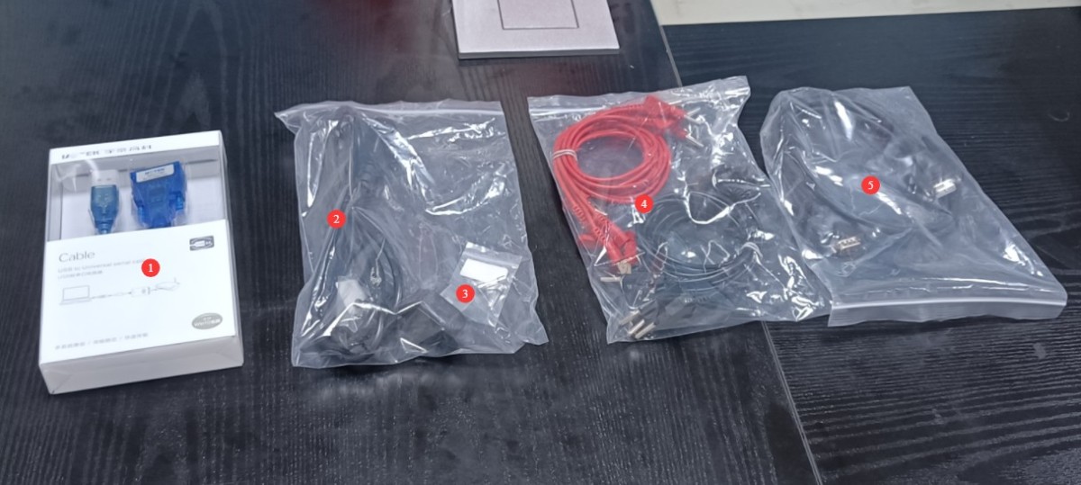
الرقم 1-1
1.2.3 تنزيل المستندات الإلكترونية
We have already sent download links for the electronic user manual, software, calibration certificate, warranty card, and other items via email at the time of shipment. Please download them promptly. If you have not received the email, please contact us to request the download links again.
2. احتياطات السلامة
2.1 السلامة الكهربائية
قبل توصيل سلك الطاقة، تأكد من أن جهد التيار الكهربائي هو ٢٢٠ فولت تيار متردد ±١٠٪، وأن التردد ٥٠ هرتز أو ٦٠ هرتز. يجب استخدام مقبس ثلاثي الأطراف مزود بتأريض وقائي، ويجب ألا تتجاوز مقاومة التأريض الوقائي ٤ أوم. لا تقم أبدًا بقطع أو فصل سلك التأريض الوقائي، لأن ذلك يُعرّضك لخطر الصعق الكهربائي.
2.2 السلامة البيئية
Do not use in environments with flammable or explosive materials, strong electromagnetic interference, high temperatures and humidity, or excessive dust levels. Operating environment: Temperature 5°C to 35°C, relative humidity ≤ 65% RH.
2.3 إجراءات التشغيل
Before connecting the wires, the power supply to the sample load must be disconnected; do not connect wires while the circuit is energized. Connect voltage leads in parallel and current leads in series; under no circumstances should a current circuit be connected to a voltage terminal or a voltage circuit to a current terminal. Pay attention to the positive and negative polarities when performing DC measurements. After connecting the wires, tighten the terminals and ensure that no bare wires are exposed to prevent short circuits or electric shock.
When measuring high-frequency signals, keep the wiring as short as possible and use thick, multi-strand wire; route the wiring away from the metal casing of the equipment to minimize interference from distributed capacitance.
3. تشغيل المعدات
3.1 مقدمة عن اللوحة الأمامية
See Figure 3-1. Note: Using the desktop software makes operation more convenient and eliminates the need to use the front panel of the device; if you need to print a test report, you must also do so through the software. If you use the software, you only need to operate the power switch and load switch on the front panel.
| رقم الهاتف | ملاحظات |
| ① | Input Parameter Display |
| ② | Output Parameter Display |
| ③ | Equipment Power Switch |
| ④ | Load Power Switch: Turns the load power on or off |
| ⑤ | Peak Lamp Current “Range” Button: Selects the current range when starting the test |
| ⑥ | Press the “Harmonics” key to select the function: Press this key to initiate the harmonic analysis; the analysis takes approximately 1 second. Once the analysis is complete, the total voltage harmonics are displayed in the voltage window, the total current harmonics in the current window, the THD (abbreviation for Total Harmonic Distortion) in the power window, and the SPEC (harmonic indicator) in the “Power/Order” window. Press the “Harmonics” key again to exit the harmonic analysis. |
| ⑦ | On the Harmonic Analysis screen, press the “▲” or “▼” keys to display the voltage and current harmonic components from the 0th to the 50th order. |
| ⑧ | Input Function: Select the “Wideband” button: Press this button to select the frequency response—narrowband or wideband—for input characteristic testing under steady-state conditions. When the corresponding LED is lit, the setting is wideband (45 Hz–1 MHz); when the LED is off, the setting is narrowband (45 Hz–5 kHz). |
| ⑨ | To select the input function, press the “HZ/°” key: Each time you press this key, the “PF/DF” window alternates between displaying the power factor and the phase shift factor. |
| ⑩ | Press the “Start” button: Press this button to initiate the startup test; the corresponding indicator light will illuminate, and “STR-” will appear in the display window. At this point, turn off the load power switch. After allowing the unit to cool slightly, turn the load switch back on. The instrument will then begin data acquisition, and “STR-” will flash on and off in the display window. Once the test is complete, the corresponding parameters will be displayed. Once a test is complete, the instrument enters a standby state. To perform the next test, press the Start button again. To exit the startup test, press the Steady-State button. |
| ⑪ | Press the “Average” button. When this button is pressed, the startup test interface will display the average startup current and startup energy efficiency in the “Peak Ratio/Average/Energy Efficiency Index/Ripple” window. |
| ⑫ | Steady-State “Test” Button: After the instrument powers on, it automatically enters steady-state testing; when the instrument is in the startup test mode, pressing this button returns it to steady-state testing. |
| ⑬ | Steady-State “Average” Button: Press this button to illuminate the “Average” indicator in the current display window. At this point, the current value shown in this window represents the average current of the lamp. |
| ⑭ | Steady-state “Ripple” button: Press this button to display the ripple current (A/mA indicator lit) and the energy efficiency coefficient (% indicator lit) in the energy efficiency coefficient/ripple window. |
| ⑮ | Steady-state “Latch” key: Press this key to latch the current test data for reading and analysis. Press any key again to exit the latch mode. |
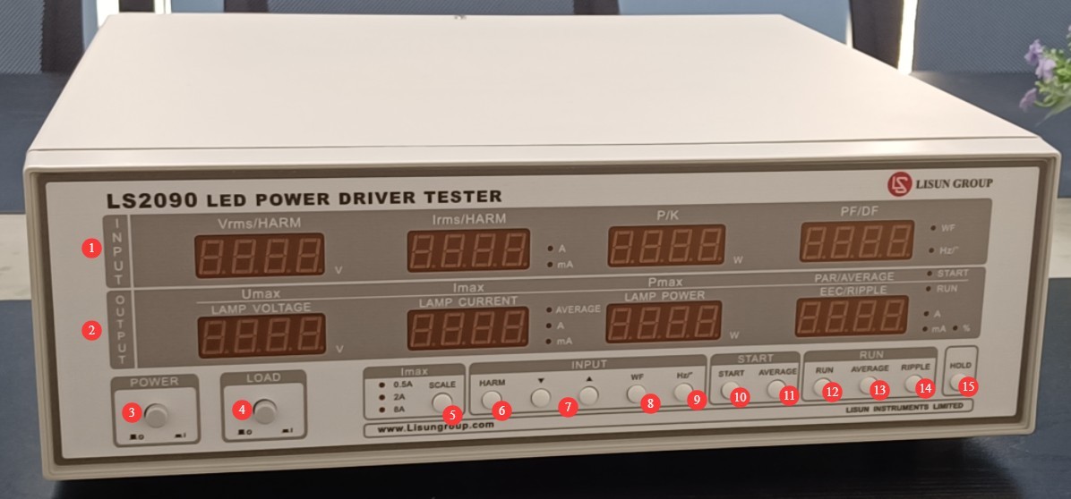
الرقم 3-1
3.2 مقدمة عن اللوحة الخلفية والأسلاك
Note: To ensure safety during operation, make sure the load power switch on the front panel of the equipment is in the off (up) position before connecting the wires.
3.2.1 Using LED Light Sources
| رقم الهاتف | ملاحظات |
| ① | Power cord jack, for connecting the device to an appropriate power source |
| ② | Equipment Input Power Supply Fuse |
| ③ | طرف التأريض الوقائي: يتم توصيله داخليًا بطرف التأريض الخاص بسلك الطاقة. إذا كان سلك الطاقة يوفر تأريضًا وقائيًا كافيًا، فلا داعي لتوصيل هذا الطرف. |
| ④ | Load Input Power Supply Fuse |
| ⑤ | RS-232 communication cable, connected to a computer, or connected to a computer via an RS-232-to-USB adapter cable |
| ⑥ | V voltage terminal: Connect the load’s input power supply cable to this terminal and connect it to the LISUN LSP Series AC power supply or another suitable power source. |
| ⑦ | Use a jumper wire to short-circuit the two black terminals at the V and A terminals. |
| ⑧ | Connect the two red terminals on the V and A terminals to the input of the LED driver. |
| ⑨ | Connect the red and black terminals of the DUT to the output terminals of the LED driver, observing the polarity: red is positive and black is negative. |
| ⑩ | Connect the blue and yellow terminals of the LED LOAD to the LED light source. Pay attention to polarity: blue is positive and yellow is negative. |
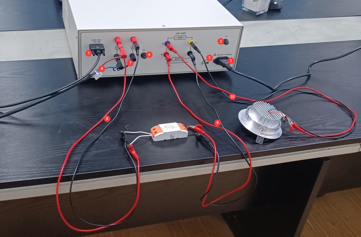
الرقم 3-2
3.2.2 Using the MB98 DC Electronic Load
See Figure 3-3. Connect the LED LOAD to the MB98 series electronic load, observing the correct polarity. All other connections are the same as in Section 3.2.1.
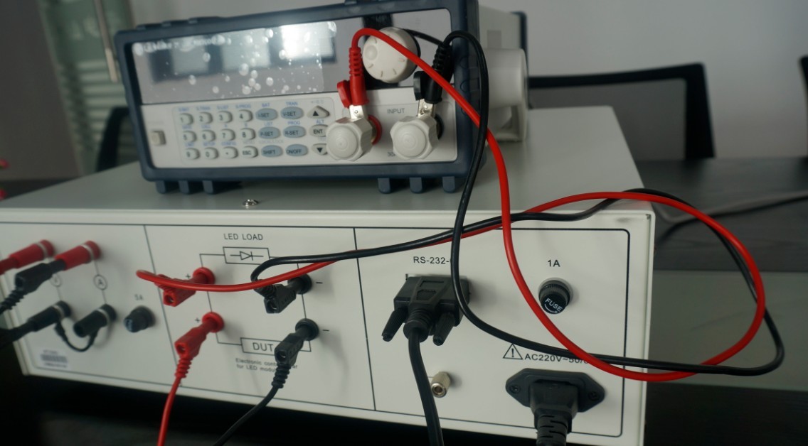
الرقم 3-3
3.3 Equipment Testing Procedures
3.3.1 Using LED Light Sources
| تعليمات | ملاحظات |
| ① | Follow the wiring instructions in Section 3.2.1. |
| ② | Powering On the Equipment |
| ③ | Based on the LED driver input parameters (such as input voltage and frequency), configure the LISUN LSP Series AC power supply (or other power supply) and start the output. |
| ④ | Press the power switch on the front panel of the device. The LED driver power supply turns on, and the LED light comes on. |
| ⑤ | See Section 3.1 for test parameters . Note: When starting the test, turn off the load power supply; wait until the sample has cooled down before turning the load power supply back on. The equipment will automatically run the startup parameters. |
| ⑥ | Press the load power switch again to snap it back up. The LED driver power supply is turned off, and the LED light goes out. |
| ⑦ | إيقاف تشغيل LISUN LSP Series AC power supply (or other power supply) output |
| ⑧ | Replace the sample for testing, or shut down the equipment |
3.3.2 Using the MB98 DC Electronic Load
| تعليمات | ملاحظات |
| ① | Follow the wiring instructions in Section 3.2.2. |
| ② | Turn on the equipment; turn on the electronic load. |
| ③ | Based on the LED driver’s output parameters (voltage, current), configure the electronic load (you need to set either the voltage or current; using voltage as an example, press V-SET twice to set the voltage, then press ENT to confirm), and then press ON/OFF to start the output. |
| ④ | Based on the LED driver’s input parameters (such as input voltage and frequency), configure the LISUN LSP Series AC power supply (or other power supply) and start the output. |
| ⑤ | Press the load power switch on the front panel of the device. The LED driver power supply turns on, and the electronic load displays the current voltage and current values of the LED driver output. |
| ⑥ | See Section 3.1 for test parameters . Note: When starting the test, turn off the load power supply; once the sample has cooled, turn the load power supply back on, and the equipment will automatically initiate the test. |
| ⑦ | Press the load power switch again to make it spring back. The LED driver power supply is turned off. |
| ⑧ | إيقاف تشغيل LISUN LSP Series AC power supply (or other power supply) output |
| ⑨ | Press the ON/OFF switch on the electronic load to turn off the output. |
| ⑩ | Replace the sample for testing, or turn off the equipment and electronic load. |
4. Software Operation (Using the LS2090-IEC Software as an Example)
4.1 تثبيت البرنامج
Software System Requirements: Computers running Windows 7 or later.
استخدم LS2090 connects to the computer via an RS-232 cable. If the computer does not have an RS-232 port, you will need to use an RS-232-to-USB adapter cable to connect the two devices.
انظر الشكل 4-1 للاطلاع على حزمة تثبيت البرنامج.
| رقم الهاتف | ملاحظات |
| ① | LS2090 software—please double-click to install |
| ② | RS-232-to-USB Adapter Driver: If you are using an RS-232-to-USB adapter, please double-click to install it. |

الرقم 4-1
4.2 نظرة عامة على البرنامج
4.2.1 Software Start Screen
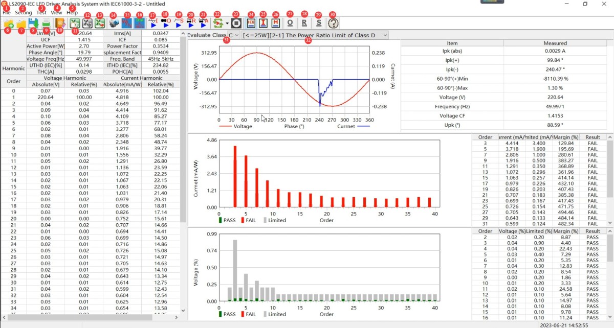
انظر الشكل 4-2.
| رقم الهاتف | ملاحظات |
| ① | File: New, Open, Save, Save As, Print, Print Preview, Exit |
| ② | Settings: System Configuration, Product Information |
| ③ | Testing: Input Characteristic Testing, Output Characteristic Testing, Start-up Characteristic Testing, Input/Output Testing, Start-up Input/Output Testing |
| ④ | View: View the IEC 61000-3-2 report, view input characteristics, view harmonic content, view output characteristics, view startup characteristics, view input and output, wideband |
| ⑤ | Help: Software Version Information, Switch Between Chinese and English |
| ⑥ | New: Create a new blank test file in .lpdx format |
| ⑦ | Open: Open a saved test file in .lpdx format |
| ⑧ | Save: Save the test file in .lpdx format |
| ⑨ | تقرير اختبار الطباعة |
| ⑩ | معلومات المنتج |
| ⑪ | Clear: Clear the data from the Excel list |
| ⑫ | Add: Add the current test data (excluding waveform data) to the Excel list. |
| ⑬ | Export: Exports all test data added to the Excel list so you can view it in Excel. |
| ⑭ | نظام التكوين |
| ⑮ | Wideband (press to select wideband; release to select narrowband): In steady-state conditions, you can select either the narrowband (45 Hz–5 kHz) or wideband (45 Hz–1 MHz) frequency response for input characteristic testing. |
| ⑯ | Switch the display units for total harmonic current: Permitted harmonic current in A/per watt; Permitted harmonic current in mA/W |
| ⑰ | Input Characteristics Testing |
| ⑱ | Output Characteristics Testing |
| ⑲ | Launch Feature Testing |
| ⑳ | اختبار الإدخال/الإخراج |
| ㉑ | Start Input/Output Testing |
| ㉒ | Continuous Testing: Continuous Testing of Input Characteristics, Continuous Testing of Output Characteristics, Continuous Testing of Input and Output |
| ㉓ | Stop Test: While in continuous test mode, click to stop the test |
| ㉔ | View the IEC 61000-3-2 Report |
| ㉕ | View Input Characteristics |
| ㉖ | View Harmonic Content |
| ㉗ | View Output Characteristics |
| ㉘ | View Input and Output |
| ㉙ | View Startup Features |
| ㉚ | معلومات إصدار البرنامج |
| ㉛ | Harmonic Limitation Standards: For example, if your load consists of LED lighting fixtures, select Class C. |
| ㉜ | Five harmonic limitation standards are used to evaluate total current distortion (THD) and voltage harmonic content. Note: For devices rated at ≤25 W, there are three evaluation criteria; meeting any one of them is sufficient. |
الرقم 4-2
4.2.2 System Configuration Interface
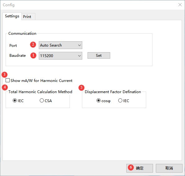
انظر الشكل 4-3.
| رقم الهاتف | ملاحظات |
| ① | Baud rate: 115200 by default; no changes needed |
| ② | Select “Auto Detect,” and the software will automatically detect the communication port. If detection fails, please check the communication cable connection and ensure the driver is installed. |
| ③ | Is the unit for the absolute value of harmonic current mA/W? |
| ④ | Total Harmonic Distortion Calculation Method: IEC (default) or CSA |
| ⑤ | Phase Shift Factor Definition: COSφ (default) or IEC |
| ⑥ | انقر فوق "موافق" للحفظ. |
الرقم 4-3
4.2.3 Product Information Screen
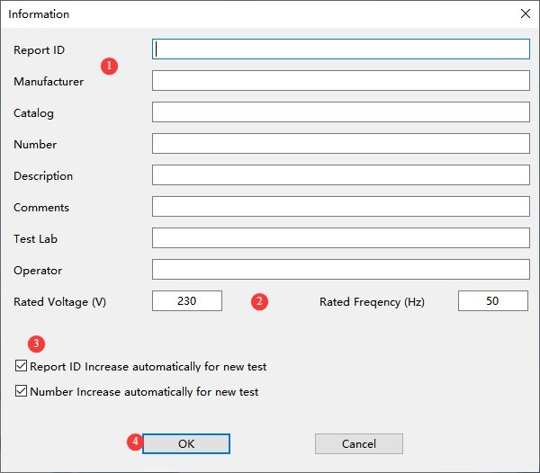
انظر الشكل 4-4.
| رقم الهاتف | ملاحظات |
| ① | أدخل التقارير والمنتجات ومعلومات الاختبار |
| ② | Enter the sample’s rated voltage and rated frequency correctly. |
| ③ | Reports, Auto-Increment Function for Product Numbers |
| ④ | انقر فوق "موافق" للحفظ. |
الرقم 4-4
4.3 Software Testing Procedures
| تعليمات | ملاحظات |
| ① | Follow the wiring instructions in Section 3.2. |
| ② | Powering On the Equipment |
| ③ | Operate the equipment as described in Section 3.3. |
| ④ | Refer to Section 4.2.2 to verify that software communication is functioning properly, and configure settings as needed. |
| ⑤ | Refer to Section 4.2.3 to correctly enter LED driver product information |
| ⑥ | Refer to Section 4.2.1 for instructions on conducting tests, viewing test information, exporting test files, and printing test reports via the software interface. Note : When starting a test, follow the software prompts to turn off the load power supply on the front panel of the device; wait until the sample has cooled before turning the load power supply back on. The software will automatically set the test startup parameters. |
5. الصيانة اليومية للمعدات والعناية بها
5.1 الصيانة الروتينية
5.1.1 التنظيف اليومي
Be sure to turn off the power and unplug the power cord before cleaning. We recommend wiping the unit with a soft, antistatic cotton cloth and a mild detergent; do not spray liquids directly onto the unit. Do not use chemical solvents such as benzene, toluene, or acetone.
5.1.2 عمليات التفتيش الروتينية
Before each use, check the power cord and terminal connections to ensure there are no loose connections or signs of burn damage; after turning on the unit, verify that the indicator lights and display are functioning properly.
5.2 مواصفات التخزين
5.2.1 متطلبات بيئة التخزين
درجة الحرارة: من 5 درجات مئوية إلى 35 درجة مئوية؛ الرطوبة النسبية: ≤65% رطوبة نسبية؛ بيئة جافة وخالية من الغبار والغازات المسببة للتآكل.
5.2.2 عمليات التخزين طويلة الأجل
Turn off the power and unplug all cables; clean the equipment and wrap it in dust-proof film; power it on for 30 minutes each month to prevent moisture damage to the components.
5.3 متطلبات فترة المعايرة
لضمان دقة القياس وموثوقية تشغيل الجهاز، يُوصى بإرساله دوريًا إلى مختبر قياسات معتمد تابع لجهة خارجية لإجراء المعايرة. يُوصى بإجراء المعايرة كل 12 شهرًا. ويمكن للمستخدمين تحديد فترة المعايرة المناسبة بناءً على وتيرة الاستخدام والظروف البيئية ومتطلبات نظام الجودة.
6. استكشاف الأخطاء وإصلاحها وحل المشكلات الشائعة
| أعراض الخلل | الأسباب المحتملة | العملية |
| تعذر تشغيل الجهاز | سلك الطاقة غير مُحكم، فيوز محترق | Turn off the power and check the connection of the input power supply cord; turn off the power, troubleshoot for short circuits or overloads, replace the fuse with one of the same rating, and do not increase the current rating. |
| The load still does not respond after the load power switch is turned on | Incorrect wiring polarity for the DUT or LED LOAD | Follow the troubleshooting steps in Section 3.2. Be sure to observe the correct polarity when connecting the DUT and LED LOAD terminals; failure to do so may affect load operation or even damage the equipment. |
| فشل في التواصل | Communication cable connection error / Driver not installed, baud rate mismatch | See Section 3.2 for troubleshooting wiring; see Section 4.1 for troubleshooting driver installation; see Section 4.2.2 for troubleshooting settings. |
| البيانات المعروضة لم تتغير. | Latch Function Triggered | Refer to Section 3.1 to check and disable the latch function. |
7. قائمة التعبئة
| رقم | الاسم | الكمية |
| ① | LS2090 LED Driver Comprehensive Performance Tester | 1 حدة |
| ② | RS-232 to USB Adapter Cable | 1 قطعة |
| ③ | السلطة الحبل | |
| ④ | الصمامات الغيار | 2 |
| ⑤ | Red and Black Test Leads | مجموعات 5 |
| ⑥ | كابل اتصال RS-232 | 1 قطعة |