
 الإنجليزية
 中文简体
中文简体 Русский
 Español
 Português
 Türkçe
 العربية
 Deutsch
 Polski
 Italiano
 Français
 한국어
한국어 ไทย
ไทย Tiếng Việt
 日本語
日本語





























محاكي تغير الجهد ثنائي القطب رباعي الأرباع
مستخدم المالكين
قابل للتطبيق LISUN models: LIS-APS-40100K300、LIS-APS-4010K300、LIS-APS-40150K300、LIS-APS-40200K300、LIS-APS-4020K300、LIS-APS-40300K300、LIS-APS-4030K300、LIS-APS-4050K300、LIS-APS-4070K300、LIS-APS-80100K300、LIS-APS-8010K300、LIS-APS-80150K300、LIS-APS-80200K300、LIS-APS-8020K300、LIS-APS-80300K300、LIS-APS-8030K300、LIS-APS-8050K300、LIS-APS-8070K300
1. فهم أساسي للمعدات
1.1 تصنيف النموذج
| LISUN الموديل | LIS-APS-4010K300 | LIS-APS-4030K300 | LIS-APS-8050K300 | LIS-APS-80100K300 |
|---|---|---|---|---|
| خصائص الإخراج | Four-Quadrant Bipolar | |||
| Rated Output Voltage Un | ±40 V DC/AC | ±80 V DC/AC | ||
| Rated Output Current In | 0 to ±10 A | 0 to ±30 A | 0 to ±50 A | 0 to ±100 A |
| Transient peak current Ip | 2 times the rated current, duration 20–200 ms | |||
| Frequency Range (Sine Wave) | DC–300 kHz (output error < 0.1%) | |||
| طريقة الإخراج | Constant voltage, constant current. (Output accuracy: 0.05%; Setting accuracy: 1 mV/1 mA) | |||
| معدل ارتفاع الجهد | ≥15 فولت/ميكروثانية | |||
| سعة جهد التيار المتردد | >30 Vpp @ 100 kHz; >10 Vpp @ 300 kHz | |||
| سعة التحميل | At full AC load, VPP drops by <200 mV | |||
| طريقة إخراج التردد | Fixed, Linear, Logarithmic | |||
| مصدر الممانعة | Adjustable from 0 mΩ to 500 mΩ (resolution: 1 mΩ, accuracy: <±5%). Also supports external resistance to meet specific automotive manufacturer standards. | |||
| تموج الجهد | <10 mVrms (ripple and noise: <30 mVpp) | |||
| تحرير الموجات المدمجة | ISO 7637-2 P2b and P4 / Linear / DC / Sine wave / Square wave / Triangle wave / Exponential wave / Arbitrary waveform; supports frequency sweeping | |||
| Number of Editable Steps for Combined Waves | ما يصل إلى 500 خطوة | |||
| Minimum editable time for composite waves | 5 µs | |||
| Count the points on an arbitrary waveform | ≤ 16000,000 | |||
| Editable point spacing for arbitrary waves | 0.1 ميكروثانية - 1 ثانية | |||
| تنسيق الموجة العشوائية | إكسل، CSV | |||
| ميزات الحماية | Features overcurrent, overvoltage, short-circuit, and overtemperature الحماية | |||
| نظام التحكم | 10.1 بوصة Chinese-English Android Capacitive Touchscreen Display + Supports Remote Control via PC Software | |||
| تحليل أخذ العينات بتقنية FFT المتموجة | The built-in oscilloscope displays the output waveform in real time. | |||
| أخذ العينات الحلقية المغلقة بتقنية التراكب المتموج | Equipped with built-in ripple voltage and current probes, it enables direct closed-loop ripple testing at a distance of 10 cm in accordance with ISO 16750-2:2023, Figure 5. | |||
1.2 المعايير المعمول بها
| رقم قياسي | عنوان قياسي |
|---|---|
| غب / T شنومكس-شنومكس | الظروف البيئية والاختبارات الخاصة بالمعدات الكهربائية والإلكترونية في المركبات البرية - الجزء الثاني: الأحمال الكهربائية |
| غب / T شنومكس-شنومكس | Test Methods for Electromagnetic Disturbances Caused by Conduction and Coupling in Electrical and Electronic Components of Road Vehicles—Part 2: Conducted Transient Emissions and Immunity Along Power Lines |
| SMTC 38000001-2012 | General Testing Requirements for Automotive Electronic and Electrical Components |
| إسو شنومكس-شنومكس: شنومكس | المركبات البرية - الظروف البيئية واختبار المعدات الكهربائية والإلكترونية - الجزء 2: الأحمال الكهربائية |
| ايزو 7637-2:2021 | Road Vehicles—Electrical Disturbances from Conduction and Coupling—Part 2: Electrical Transients Conducted Solely Along Power Supply Lines |
| م 124 | Electrical and Electronic Components in Motor Vehicles Weighing Up to 3.5 Metric Tons—Requirements, Test Conditions, and Tests for the 12-Volt On-Board Electrical System |
| LV 148-E09 | المكونات الكهربائية والإلكترونية في المركبات الآلية - متطلبات نظام الكهرباء الداخلي 48 فولت وشروط الاختبار |
| فولكس فاجن 80000:2023 | Geometric Tolerance and Quality Control Specifications for Automotive Components |
| GS 95024-2:2011 | Electrical and Electronic Components in Motor Vehicles—Supplementary Requirements and Tests for 12V On-Board Electrical System Components |
| GMW 3172:2023 | General Specifications for Electrical and Electronic Components – Environmental and Durability |
1.3 سيناريوهات التطبيق
The LIS-APS Series Four-Quadrant Bipolar Voltage Variation Simulator is a high-precision power supply simulation device that supports bidirectional energy flow. Based on a fully controlled H-bridge topology, it enables disturbance-free transitions across all four operating quadrants and provides seamless switching between positive and negative voltage and current outputs.accurately simulating dynamic voltage changes, transient pulses, polarity reversals, and operating conditions such as open circuits, short circuits, and wire disconnections. It also features customizable waveform editing, adjustable impedance, and wide-frequency ripple superposition, making it a core piece of equipment for power supply adaptability testing in fields such as automotive electronics and rail transit.
Applications: In the automotive electronics sector, it simulates operating conditions such as fluctuations in vehicle battery voltage, start-stop cycles, and open circuits or short circuits in wiring harnesses to verify the immunity and reliability of components such as ECUs, BMSs, and vehicle lights; in the rail transit and aerospace sectors, it performs power supply adaptability testing on onboard electronic equipment; in industrial control and medical electronics, to verify the operational stability of equipment under power supply fluctuations; and in energy storage and motor applications, to simulate voltage and current characteristics during energy regeneration.
2. احتياطات الاستخدام
2.1 متطلبات البيئية
درجة الحرارة المحيطة: 23 درجة مئوية ± 5 درجة مئوية؛ الرطوبة النسبية: 45-75%، بدون تكثيف؛ الارتفاع: ≤2000 متر؛ لا توجد اهتزازات قوية أو تداخل كهرومغناطيسي في المنطقة المحيطة؛ يُحظر استخدام المعدات في البيئات المتربة أو القابلة للاشتعال أو المتفجرة بشكل صارم.
2.2 متطلبات امدادات الطاقة
Input power supply: AC 220 V ±10%, 50 Hz; Input power: ≤1 kW; The power supply must be reliably grounded, with a grounding resistance of ≤4 Ω; It is recommended to use a voltage-regulated power supply to prevent power grid fluctuations from affecting test accuracy.
2.3 مبادئ الأسلاك
Use power cables with the specified wire gauge to prevent the conductors from overheating under high current conditions; keep test cables as short as possible and route them in parallel to minimize the impact of parasitic parameters; ensure that the DUT (Device Under Test) enclosure is reliably connected to the equipment’s protective ground; and route signal cables separately from power cables to avoid cross-interference.
2.4 إرشادات السلامة التشغيلية
Wear insulated protective gear; before testing, ensure all connections are secure and that there are no exposed conductors; do not plug in or unplug test cables during testing to avoid arc burns; do not touch the DUT or test fixtures while the pulse is being output; if you hear unusual noises, smell an unusual odor, or see smoke, immediately disconnect the power; During prolonged continuous testing, ensure the equipment is properly ventilated for heat dissipation.
3. نظرة عامة على المعدات والأسلاك
3.1 اللوحة الامامية
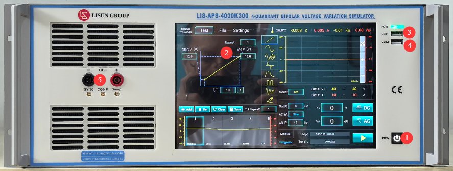
انظر الشكل 3-1.
| رقم الهاتف | ملاحظات |
|---|---|
| ① | مفتاح تشغيل الجهاز: اضغط لفترة وجيزة لتشغيله؛ اضغط مع الاستمرار لإيقاف تشغيله. |
| ② | شاشة لمس سعوية ٤.٧ بوصة |
| ③ | منفذ USB1: يستخدم بواسطة LISUN يستخدمه المهندسون لتصحيح أخطاء الأجهزة؛ ولا يحتاج المستخدمون إلى استخدامه. |
| ④ | منفذ USB 2.0، والذي يمكن استخدامه لتوصيل فأرة للتحكم في شاشة اللمس، أو لتوصيل ذاكرة فلاش USB لترقية البرنامج أو تحديث ملفات قاعدة البيانات |
| ⑤ | Output connector; observe polarity. Used to connect directly to the DUT for testing. |
3.2 لوحة الظهر
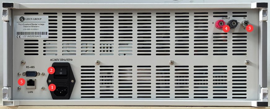
انظر الشكل 3-2.
| رقم الهاتف | ملاحظات |
|---|---|
| ① | مقبس سلك الطاقة والفيوز؛ تأكد من تأريض مصدر الطاقة المدخل بشكل صحيح. |
| ② | Circuit breaker, main input power supply switch for the equipment |
| ③ | طرف التأريض الوقائي: إذا لم يكن لمصدر الطاقة المدخل اتصال أرضي موثوق به، فيجب توصيل هذا الطرف بالأرض بشكل منفصل. |
| ④ | Output jack—pay attention to polarity; this jack functions identically to the front-panel output jack. When using it as a power source, connect it to other devices using a cable. |
| ⑤ | RS485 interface/LAN port, which can be connected to a computer to use the host software (as a backup). The host software offers the same functionality as the touchscreen; please contact us if needed. |
3.3 مقدمة عن الملحقات
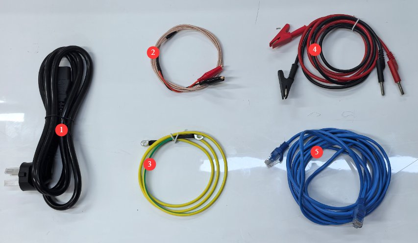
انظر الشكل 3-3.
| رقم الهاتف | ملاحظات |
|---|---|
| ① | السلطة الحبل |
| ② | AC Output Voltage Calibration Cable, Spare. When outputting high-frequency AC voltage, if you observe that the output voltage attenuates over time, use this cable to calibrate the voltage. Please contact us if you need to use it. |
| ③ | سلك ارضي |
| ④ | Test lead, used to connect the output port on the device’s front panel to the DUT |
| ⑤ | كابل إيثرنت، يُستخدم لتوصيل جهاز كمبيوتر ببرنامج مضيف |
4. مقدمة لبرنامج الشاشة اللمسية
4.1 واجهة الاختبار
4.1.1 Use as a Power Source
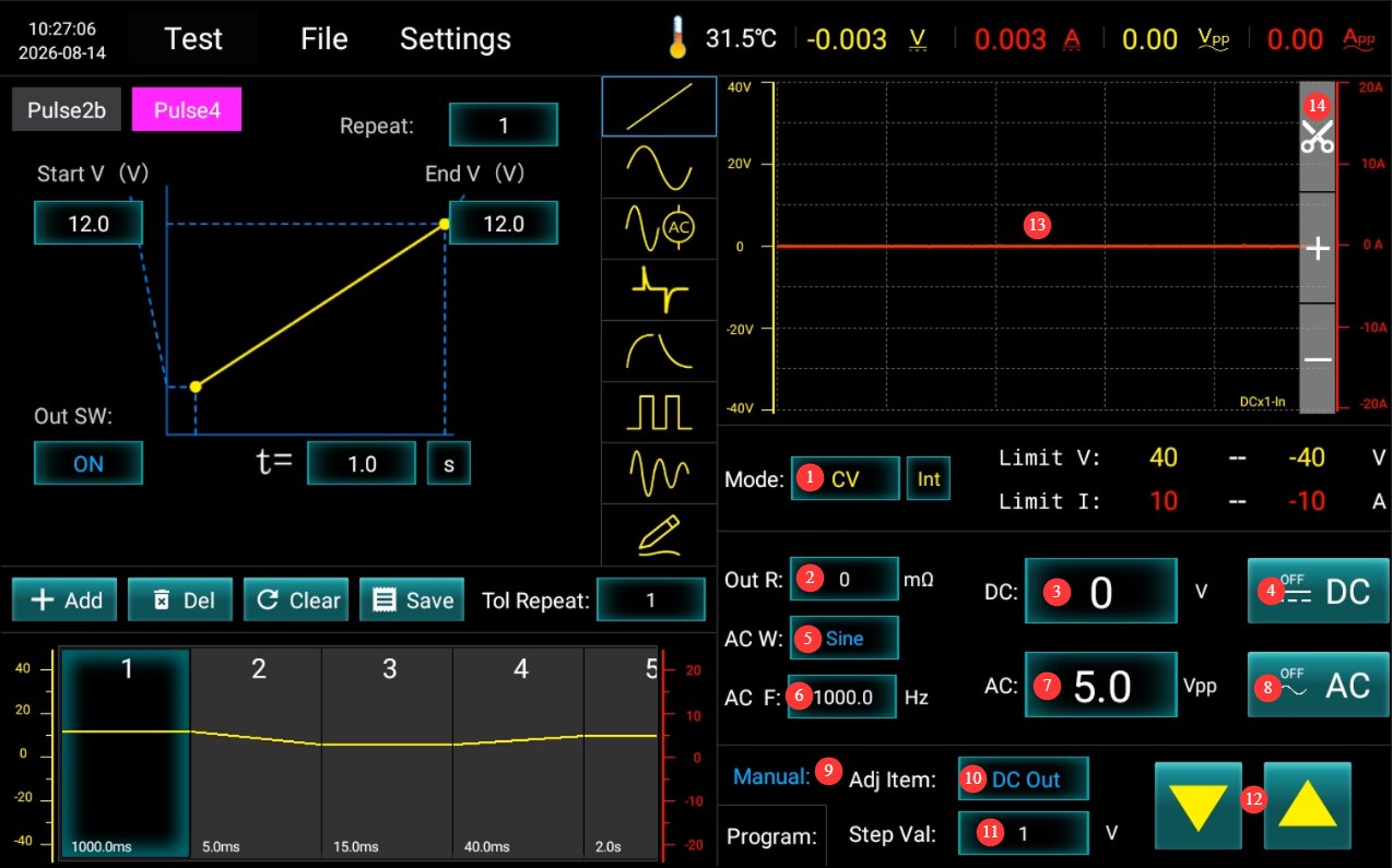
انظر الشكل 4-1.
| رقم الهاتف | ملاحظات |
|---|---|
| ① | Set the output mode for DC: CV for constant voltage, CC for constant current |
| ② | Set the Output Resistance |
| ③ | Set DC Output Voltage/Current |
| ④ | Click to turn the DC power output on or off; it can be used as a standalone output or combined with AC output. |
| ⑤ | Select an AC Waveform |
| ⑥ | Set the AC Frequency |
| ⑦ | Set the AC voltage; note that this is the Vpp value. |
| ⑧ | Click to turn the AC power output on or off; it can be output independently or combined with DC output. |
| ⑨ | Switch to Manual Adjustment |
| ⑩ | Select the regulated power supply: AC or DC |
| ⑪ | Set the step value |
| ⑫ | Click the up/down buttons to manually adjust the output according to the set increment value. |
| ⑬ | Display the current output waveform |
| ⑭ | Screenshot: Click to save a screenshot of the current output waveform to your device. |
4.1.2 Standard Operational Testing
انظر الشكل 4-2.
| رقم الهاتف | ملاحظات |
|---|---|
| ① | Here are the shortcut keys for the Pulse 2b and Pulse 4 waveforms in 12V mode. Simply click to select them—no need to adjust any parameters. |
| ② | If you need to use the Pulse 2b and Pulse 4 waveforms in 24V mode or conduct tests according to other standard specifications, you must access the database file interface to make your selection. Once selected, no parameters need to be modified. |
| ③ | Switch to Programming Mode |
| ④ | Click to run the test |
| ⑤ | Display the steps and duration of the current test |
| ⑥ | Display the current output waveform |
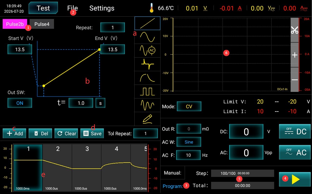
If you need to perform custom tests, refer to the table below.
| رقم الهاتف | ملاحظات |
|---|---|
| a | Waveform selection, from top to bottom: DC linear wave, AC sine wave/triangular wave/TMW pulse wave, AC test mode (constant voltage), AC closed-loop test/constant current, AC open-loop test mode, differential wave, exponential wave, square wave, decay wave, custom waveform (reserved; please contact us if you need to use this option) |
| b | Waveform Diagram and Parameter Settings |
| c | After selecting a waveform and configuring the parameters, click “Add.” |
| d | Once all settings are configured, click “Save” to save the current test parameters to the database file. |
| e | All waveforms added in sequence |
4.2 واجهة ملف قاعدة البيانات
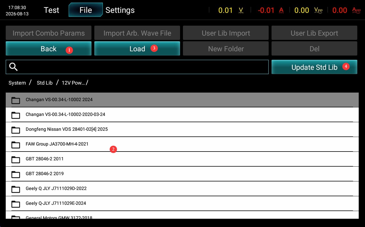
انظر الشكل 4-3.
| رقم الهاتف | ملاحظات |
|---|---|
| ① | Back to the Previous Directory |
| ② | Select the standard file you want to test |
| ③ | Double-click or click “Import” to open the test interface and run the test. |
| ④ | If you have other standard tests but do not wish to create custom tests, please contact us and send us the details of the corresponding standard. We will guide you on how to use a USB drive to update the database file directly with that standard. |
4.3 واجهة الإعدادات
انظر الشكل 4-4.
| رقم الهاتف | ملاحظات |
|---|---|
| ① | Report Storage Methods and Paths |
| ② | Closed-Loop Test Save Options and Save Paths |
| ③ | How to Save Screenshots and Where They Are Saved |
| ④ | Communication settings are set to LOCAL by default. If you need to use host computer software, you can switch to RS485 or the LAN port. Please contact us. |
| ⑤ | Security settings: Use the factory default settings; do not change them. |
| ⑥ | Test Report Parameter Settings |
| ⑦ | Probe Multiplier: This setting is only effective during AC closed-loop testing. The value set for Vpp is multiplied by this multiplier. Use the factory default setting; do not modify it. |
| ⑧ | إعدادات حجم |
| ⑨ | Combined Wave Compensation Voltage: If a compensation voltage is set here when outputting a combined waveform on the test interface, this value will be added. Use the factory default setting; do not modify it. |
| ⑩ | For overcurrent delay, use the factory default setting; do not modify it. |
| ⑪ | تبديل لغة العرض |
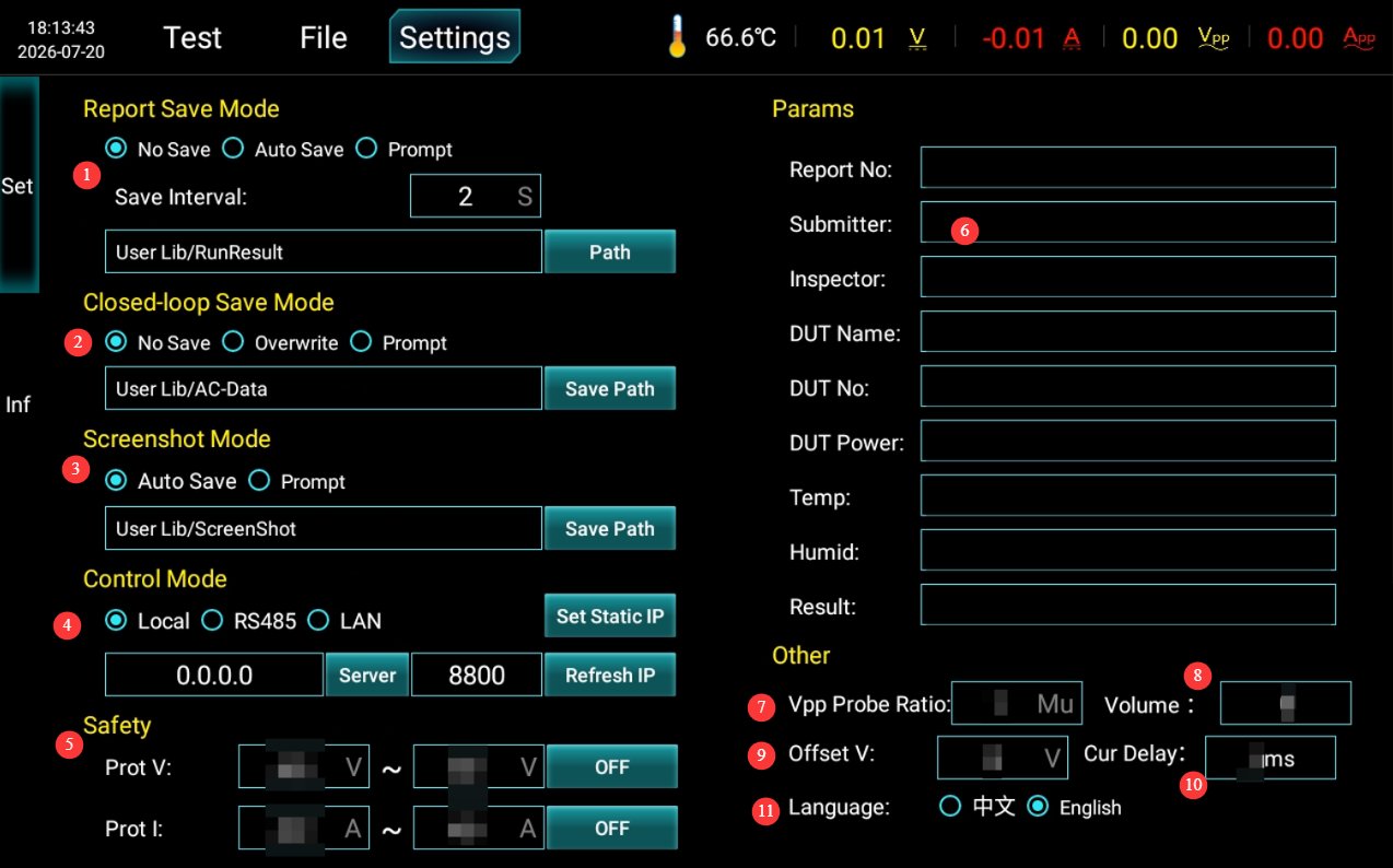
Note: We do not recommend enabling the auto-save feature. Automatically saving large numbers of waveform and report files over time will consume device storage space and may cause the touchscreen program to run slowly.
5. إجراءات الاختبار
5.1 Using It as a Power Source
Ensure that all devices are powered off; use a test cable to connect the device’s output port to the DUT’s power input port; after setting the desired power output parameters as described in Section 4.1.1, start the output; when finished, click “Disconnect Output” again.
5.2 Standard Operational Testing
5.2.1 الأسلاك
Ensure that both the device and the DUT are powered off; use a test cable to connect the device’s output port to the DUT’s power cord.
5.2.2 الاختبار التشغيلي
First, refer to Section 4.1.1 to set the appropriate power supply parameters for the DUT and enable the power supply output, ensuring that the DUT is in normal operating condition.
Then, refer to Section 4.1.2 to select the required test standard or configure the test parameters, and run the test; observe the DUT’s operating status and record any observations; wait for the test to complete—or, in case of an emergency, press the stop button to halt the test immediately.
5.2.3 تقييم النتائج
| المستوى الوظيفي | Definition of Standards | Judging Guidelines |
|---|---|---|
| الصف | During and after the application of interference, all functions of the DUT operated normally as designed, and performance parameters remained within specifications. | No functional abnormalities were observed throughout the entire process, and no intervention was required after testing—this meets the highest standards. |
| درجة ب | During the application of interference, all functions remain operational, but certain parameters may exceed their tolerance limits; once the interference is removed, all functions automatically return to their normal ranges, and the storage function maintains Class A performance. | Parameter drift and minor performance degradation are permitted during testing, but no functional failures may occur; the system must automatically recover after testing. |
| الصف C | During the application of interference, one or more functions do not operate as designed; once the interference is removed, the functions automatically return to normal. | During testing, phenomena such as functional interruptions and logical anomalies are permitted; after testing, the system should recover automatically without the need for manual intervention. |
| الصف د | Malfunction occurs while interference is present; after the interference is removed, normal operation can be restored only through simple manual steps (power cycle, reset). | Freezing, rebooting, and similar issues are acceptable, but there must be no hardware damage, and the system must be able to recover with a simple reset. |
| الصف E | During and after the interference, the function will be permanently disabled and cannot be restored without repairing or replacing the hardware. | Permanent damage; automatically deemed a failure |
Core Principle: If the DUT exhibits a Grade E performance (hardware damage, permanent loss of functionality), the test is deemed a failure regardless of the agreed-upon grade; for Grades A through D, pass/fail is determined based on the minimum acceptable grade agreed upon by the supplier and the customer.
5.2.4 إجراءات ما بعد الاختبار
تأكد من إيقاف تشغيل كل من الجهاز والجهاز قيد الاختبار؛ افصل الأسلاك من جانب الجهاز قيد الاختبار أولاً، ثم افصل الأسلاك من جانب الجهاز.
6. الصيانة اليومية للمعدات والعناية بها
6.1 التنظيف اليومي
6.1.1 جدول وإجراءات التنظيف
بعد كل استخدام: نظف سطح شاشة اللمس وأزل الغبار من لوحة الجهاز؛
أسبوعيا: نظف غلاف الجهاز والفلاتر الموجودة في فتحات التهوية؛
شهري: تنظيف الغبار من داخل المعدات (يجب أن يقوم بذلك فني متخصص).
6.1.2 طرق التنظيف
Wipe the exterior with a clean, soft, lint-free cloth; use a dedicated screen cleaner for the touchscreen; clean the vents with a soft-bristled brush and use a vacuum cleaner if necessary; do not use corrosive solvents such as acetone.
6.2 التفتيش الدوري
تحقق من سلك الطاقة بحثًا عن أي تلف أو تآكل؛ وتأكد من أن وصلة التأريض محكمة؛ وتأكد من أن المروحة تعمل بشكل طبيعي؛ وتأكد من استجابة الأزرار وشاشة اللمس؛ وتحقق من كتل التوصيل بحثًا عن أي أكسدة أو وصلات مفكوكة.
6.3 التخزين والمناولة
6.3.1 متطلبات التخزين طويل الأجل
Storage Conditions: Temperature -10°C to +50°C, humidity ≤ 85%; Clean the equipment and apply dust protection before storage; Power it on once every 3 months, running it for at least 30 minutes each time; Avoid stacking or applying heavy pressure to prevent the panel from warping.
6.3.2 احتياطات التعامل
Unplug all external cables before moving the device; use the original packaging and ensure it is properly cushioned and protected; keep the device upright during transport and avoid harsh vibrations; when lifting, grip the bottom and sides of the device—do not lift by the panel.
6.4 متطلبات فترة المعايرة
لضمان دقة القياس وموثوقية تشغيل الجهاز، يُوصى بإرساله دوريًا إلى مختبر قياسات معتمد تابع لجهة خارجية لإجراء المعايرة. يُوصى بإجراء المعايرة كل 12 شهرًا. ويمكن للمستخدمين تحديد فترة المعايرة المناسبة بناءً على وتيرة الاستخدام والظروف البيئية ومتطلبات نظام الجودة.
7. استكشاف الأخطاء وإصلاحها وحل المشكلات الشائعة
| أعراض الخلل | الأسباب المحتملة | العملية |
|---|---|---|
| الجهاز لا يعمل | The input power supply main power switch on the back is not turned on, or the fuse has blown | Turn on the input power supply switch located at the power cord receptacle on the back of the unit; check the fuse, and if it has blown, replace it with a fuse of the same rating. |
| عطل في شاشة اللمس بعد التشغيل | تجمد النظام، كابل شريطي مفكوك | إذا استمرت المشكلة بعد إعادة التشغيل، فافصل الطاقة، وأزل الغطاء الخارجي للجهاز، وتحقق مما إذا كان كابل شريط شاشة اللمس مفكوكًا. |
| Test Stopped Automatically Midway | Over-temperature protection triggered, overcurrent/overvoltage protection triggered | Check whether the equipment’s ventilation is obstructed and whether the ambient temperature is too high; check the DUT for short circuits or overloads. |
| لم يتم التعرف على ذاكرة الفلاش USB | USB drive format is incompatible or has excessive capacity | استخدم محرك أقراص USB مهيأ بنظام FAT32 بسعة لا تزيد عن 32 جيجابايت؛ إذا لم ينجح ذلك، فجرب محرك أقراص USB مختلفًا. |
| No voltage/current after output is enabled | DUT Wiring Abnormality, Protection Function Triggered | After disconnecting the output, verify that the DUT is wired correctly and that there are no open circuits or short circuits; check for any overvoltage, overcurrent, or overtemperature warnings, and retry after resolving the issue. |
| Abnormal Output Voltage/Current Accuracy | Improper output resistance settings; long-term lack of calibration | Verify that the source impedance parameters meet the test requirements; contact a third-party metrology organization to perform calibration. |