
 الإنجليزية
 中文简体
中文简体 Русский
 Español
 Português
 Türkçe
 العربية
 Deutsch
 Polski
 Italiano
 Français
 한국어
한국어 ไทย
ไทย Tiếng Việt
 日本語
日本語





























نظام استقبال EMI
مستخدم المالكين
قابل للتطبيق LISUN الموديلات: EMI-9KC
1. فهم أساسي للمعدات
1.1 نظرة عامة على المنتج
1.1.1 نطاق استخدام المنتج
استخدم EMI-9KC EMI Receiver Test System is a fully automated EMI pre-test device primarily used for conducted disturbance voltage testing and radiated disturbance alternative method/pre-testing of electrical and electronic products. The system features a fully enclosed, highly conductive chassis design with excellent shielding performance and low intrinsic interference levels. Test results are presented in an internationally recognized report format, with frequency coverage spanning the entire 9 kHz to 1000 MHz band. It is widely used for EMI R& D, debugging, and compliance pre-testing of products such as lighting fixtures, household appliances, power tools, switching power supplies, information technology equipment, and multimedia devices, and can meet full-band testing requirements ranging from low-frequency conducted emissions to high-frequency radiated emissions.
1.1.2 المكونات الرئيسية للنظام
| رقم الهاتف | ملاحظات |
|---|---|
| ① EMI-9KC المتلقي | The core test unit of the system, responsible for receiving, detecting, and processing interference signals, covers a frequency range of 9 kHz to 1000 MHz. It supports three detection modes—peak (PK), quasi-peak (QP), and average (AV)—and enables fully automated testing via host computer software. |
| ② LISN-C شبكة كهربائية اصطناعية | Used for conducted emission voltage testing in the 9 kHz to 30 MHz frequency range. It provides high-frequency isolation between the equipment under test (EUT) and the power supply, simulates the mains impedance specified in the standard, standardizes test conditions, and simultaneously couples and extracts interference signals from the power cord. |
| ③CDNE-M316 شبكة فصل اقتران | Used for radiated disturbance testing via the substitution method in the 30 MHz to 300 MHz frequency range; extracts the equivalent radiated disturbance signal of the EUT through common-mode coupling. |
| ④ العزلة محول | There are two in total. Isolation Transformer supplies power to the LISN/CDNE and the device under test, providing electrical isolation between the power grid and the test circuit and reducing background interference from the power grid; Isolation Transformer low-capacity Isolation Transformer supplies power to the EMI-9KC receiver, computer, and printer, preventing peripheral devices from interfering with the test circuit. |
1.3 Equipment Configuration Verification
1.3.1 التفريغ
عند إخراج الجهاز من العلبة، تعامل معه برفق لتجنب خدش غلافه بأدوات حادة. بعد إخراجه، افحص أولاً الجزء الخارجي من الجهاز للتأكد من عدم وجود أي تشوه أو انبعاجات ظاهرة، وأن الأزرار ليست تالفة أو مفكوكة. إذا لاحظت أي خلل في الجهاز أو ملحقاته، do not turn it on. يرجى الاتصال بنا على الفور.
1.3.2 المضيف والملحقات
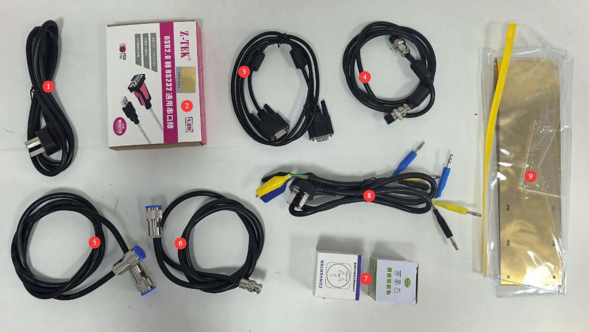
Main units: 1 each of EMI-9KC, LISN-Cو CDNE-M3162 محول عزل.
انظر الشكل 1-1 للاطلاع على المكونات الأخرى.
| رقم الهاتف | ملاحظات |
|---|---|
| ① | سلك الطاقة لـ EMI-9KC |
| ②③ | كابل اتصال RS-232 وكابل محول RS-232 إلى USB، يُستخدمان لتوصيل EMI-9KC لجهاز كمبيوتر |
| ④ | Aviation connector cable, used to connect the EMI-9KC إلى LISN-C |
| ⑤⑥ | Coaxial cable, used to connect the EMI-9KC إلى LISN-C (dual N-type connectors) or the CDNE (N-type and BNC connectors) |
| ⑦ | 10A-to-16A and 16A-to-10A adapters, compatible with LISN-C |
| ⑧ | AE and EUT connection cables, used to connect to the CDNE. Packaged with the CDNE at the factory. |
| ⑨ | Copper grounding plate, used to connect to the LISN-C grounding terminal. Packaged with the LISN at the factory. |
2. احتياطات السلامة
2.1 السلامة الكهربائية
2.1.1 سلامة مصدر الطاقة
يجب توصيل جميع المعدات بمحول العزل عبر محول عزل؛ ويُحظر التوصيل المباشر بالتيار الكهربائي الرئيسي منع حدوث ارتفاعات مفاجئة في الطاقة وخطر الصدمة الكهربائية.
استخدم EMI-9KC main unit must be connected to a stable single-phase AC 220 V ±10%, 50/60 Hz power supply; do not use the device if the power connections are loose or the cables are damaged.
2.1.2 سلامة التأريض
يجب تركيب نظام تأريض منفصل وموثوق؛ فكلما انخفضت مقاومة التأريض، زادت دقة نتائج الاختبار. ويُمنع منعًا باتًا استخدام قطب تأريض مشترك مع معدات كهربائية عالية الطاقة.
The grounding terminals and reference metal plates of all equipment must be securely connected to the grounding electrode, and the connection points must be free of corrosion and loose.
During thunderstorms, disconnect the equipment from both the power source and the ground connection to prevent damage from lightning strikes.
2.2 السلامة التشغيلية
2.2.1 Power On/Off and Connection/Disconnection Guidelines
Strictly follow the sequence: “When turning on the computer, turn on the peripherals first, then the main unit; when turning off the computer, turn off the main unit first, then the peripherals.”
Before powering on or off the EUT, you must first disconnect the coaxial cable from the receiver’s front end to prevent switching transients from damaging the receiver’s internal circuitry.
Do not connect or disconnect coaxial cables or switch the L/N phase switch on the LISN during test operation, as high-voltage pulses may damage the receiver’s RF input module.
2.2.2 حدود إشارة الإدخال
The load current for the LISN-C و CDNE-M316 must not exceed the maximum rated current of 16 A; overloading may cause the equipment to burn out.
2.3 سلامة البيئة
2.3.1 متطلبات بيئة العمل
تتراوح درجة حرارة بيئة تشغيل المعدات بين 5 و35 درجة مئوية، مع رطوبة نسبية ≤80% وبدون تكثف.
يُحظر منعاً باتاً تخزين المواد القابلة للاشتعال أو المتفجرة أو المسببة للتآكل داخل منطقة الاختبار، كما يُحظر منعاً باتاً إجراء الاختبارات التي تعمل بالطاقة في البيئات القابلة للاشتعال أو المتفجرة.
يجب عدم وضع المعدات التي تولد تداخلًا كهرومغناطيسيًا قويًا - مثل محركات التردد المتغير، ولحام القوس الكهربائي، والشواحن عالية الطاقة، وأجهزة الإرسال اللاسلكية - داخل غرفة الاختبار لتقليل تأثير الضوضاء البيئية الخلفية على نتائج الاختبار.
2.3.2 متطلبات بيئة التخزين والنقل
Equipment must be shipped in its original packaging, with proper protection against shock, moisture, and impact. Do not invert the package or subject it to heavy pressure.
يجب أن تكون درجة الحرارة المحيطة للتخزين طويل الأجل 5-35 درجة مئوية، مع رطوبة نسبية ≤80%، وتهوية جيدة، وعدم وجود غازات أكالة في الهواء.
2.4 خدمات أخرى
بالنسبة للأمور غير المشمولة في هذا الدليل، يرجى توخي الحذر أو الاتصال بنا.
3. نظرة عامة على المعدات والأسلاك
3.1 EMI-9KC المتلقي
3.1.1 اللوحة الأمامية
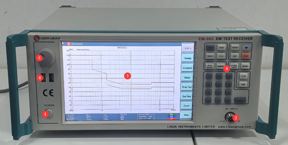
انظر الشكل 3-1.
| رقم الهاتف | ملاحظات |
|---|---|
| ① | مفتاح الطاقة |
| ② | منفذ إدخال الترددات اللاسلكية، متصل بـ LISN-C or CDNE via a coaxial cable |
| ③④⑤ | The touchscreen and on-screen control area function essentially the same as the desktop software; please refer to the software feature overview. |
| ⑥ | USB port: If a firmware update is available, you can use a USB flash drive to update it. |
3.1.2 اللوحة الخلفية
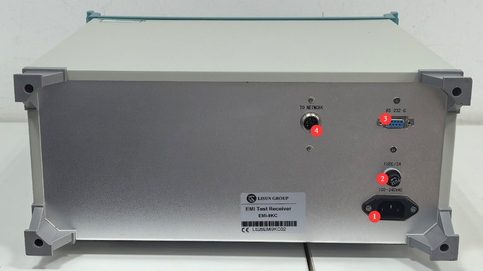
انظر الشكل 3-2.
| رقم الهاتف | ملاحظات |
|---|---|
| ① | مقبس سلك الطاقة، متصل بمحول العزل |
| ② | فتيل |
| ③ | منفذ اتصال RS-232: قم بالتوصيل بجهاز الكمبيوتر باستخدام كابل اتصال RS-232. إذا لم يكن جهاز الكمبيوتر مزودًا بمنفذ RS-232، يمكنك استخدام كابل محول RS-232 إلى USB القياسي للتوصيل. ملاحظة: تجنب استخدام كابلات أو محولات اتصال غير قياسية، فقد يتسبب ذلك في حدوث أخطاء في الاتصال. |
| ④ | Aviation cable connector; connect to the LISN-C using an aviation cable |
3.2 LISN-C شبكة كهربائية اصطناعية
3.2.1 اللوحة الأمامية
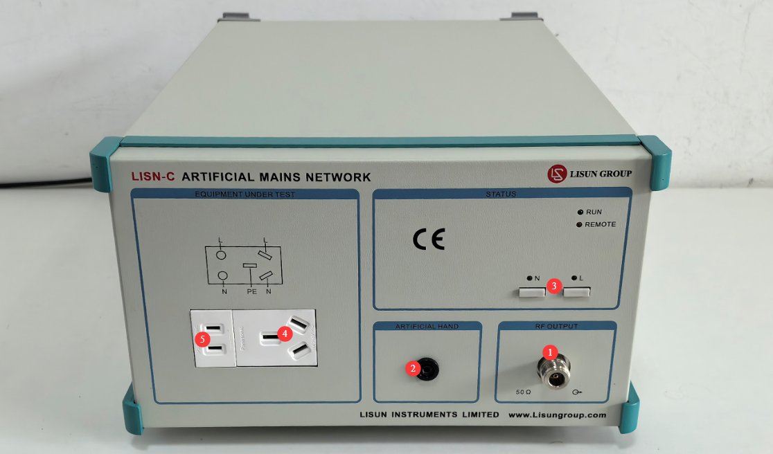
انظر الشكل 3-3.
| رقم الهاتف | ملاحظات |
|---|---|
| ① | منفذ إخراج الترددات اللاسلكية؛ قم بالتوصيل بـ EMI-9KC باستخدام محول N إلى BNC وكابل محوري |
| ② | L/N switch, used to switch between test phase and neutral lines for interference signals |
| ③ | ARTIFICIAL HAND Interface, simulated hand connection terminals, used for testing handheld devices |
| ④ | 16A three-wire power cord connection port; can be connected directly to the EUT or via a 16A-to-10A adapter plug |
| ⑤ | 10A two-conductor power cord connection port; can be connected directly to the EUT |
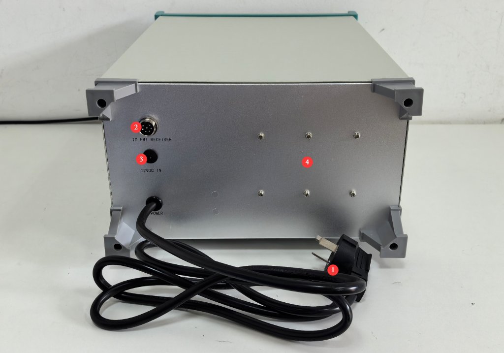
3.2.2 اللوحة الخلفية
See Figures 3-4.
| رقم الهاتف | ملاحظات |
|---|---|
| ① | سلك طاقة مزود بقابس 16 أمبير؛ يمكن توصيله مباشرة بمحول العزل أو توصيله بمحول العزل عبر قابس محول من 10 أمبير إلى 16 أمبير. |
| ② | Aviation connector; connect to the EMI-9KC using an aviation cable |
| ③ | 12V power connector; no connection required |
| ④ | طرف التأريض: قم بالتوصيل باستخدام لوحة تأريض نحاسية وفقًا للمعيار. |
3.3 شبكة فصل اقتران CDNE
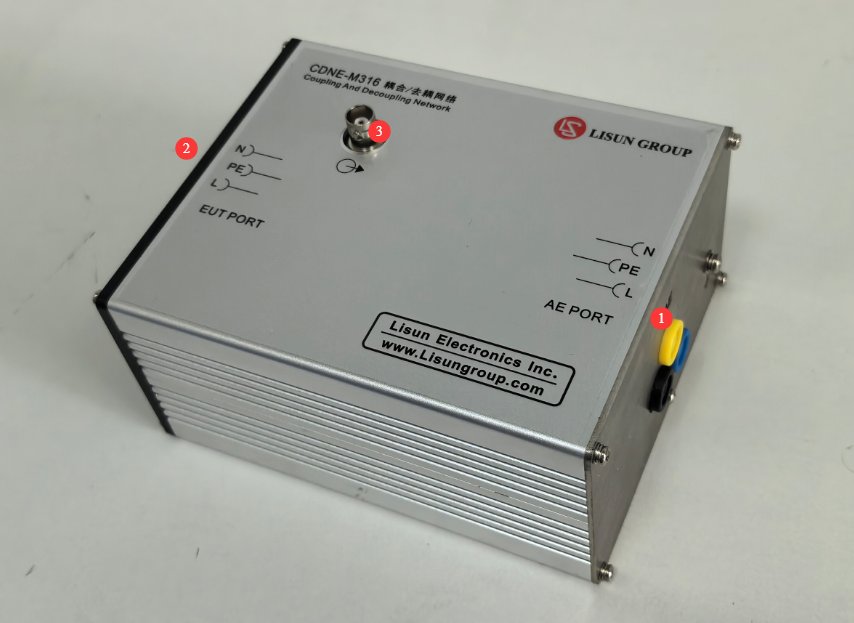
انظر الأشكال من 3 إلى 5.
| رقم الهاتف | ملاحظات |
|---|---|
| ① | منفذ AE، متصل بمحول العزل |
| ② | منفذ الجهاز قيد الاختبار، متصل بالجهاز قيد الاختبار |
| ③ | موصل خرج الترددات اللاسلكية من نوع BNC، متصل بـ EMI-9KC via a coaxial cable |
3.4 Isolation Isolation Transformer
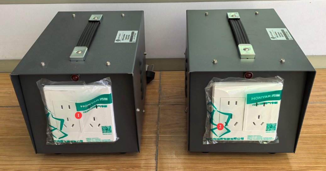
3.4.1 اللوحة الأمامية
انظر الأشكال من 3 إلى 6.
| رقم الهاتف | ملاحظات |
|---|---|
| ① | محول عزل 500 فولت أمبير يُستخدم لتوصيل EMI-9KC أجهزة الاستقبال، وأجهزة الكمبيوتر، والطابعات، وغيرها من الأجهزة. |
| ② | يُستخدم محول العزل لتوصيل LISN-C أو CDNE وتزويد الطاقة للجهاز قيد الاختبار؛ ويشمل ذلك مقبسًا واحدًا بقوة 16 أمبير. |
3.4.2 اللوحة الخلفية
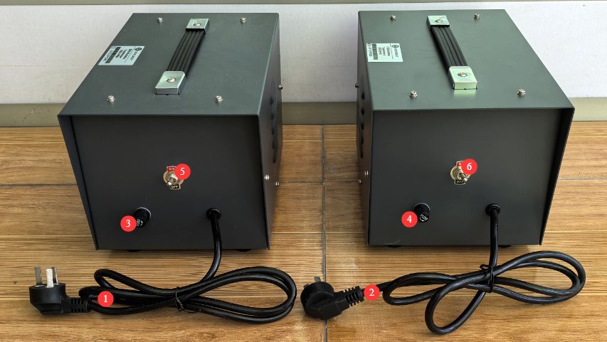
انظر الشكل 3-7.
| رقم الهاتف | ملاحظات |
|---|---|
| ①② | Simply connect Isolation Transformer to the power grid using the power cord. Isolation Transformer, which powers the EMI-9KC, should be connected to a 220V power grid; the 1kVA Isolation Transformer Transformer, which powers the EUT, must be connected to an appropriate power grid based on the EUT’s requirements. |
| ③④ | فتيل |
| ⑤⑥ | مفتاح الطاقة |
4. تثبيت البرنامج ونظرة عامة
4.1 تثبيت البرامج وبرامج التشغيل
4.1.1 متطلبات تشغيل النظام
نظام التشغيل: ويندوز 7 / ويندوز 8 / ويندوز 10 / ويندوز 11؛ يوصى باستخدام ويندوز 10؛
متطلبات الأجهزة: معالج بنتيوم أو أعلى، وذاكرة وصول عشوائي ≥2 جيجابايت، ومساحة خالية على القرص الصلب ≥1 جيجابايت، ومنفذ USB واحد متاح على الأقل؛
يوصى بدقة شاشة تبلغ 1024×768 أو أعلى.
تثبيت 4.1.2
انظر الشكل 4-1.
| رقم الهاتف | ملاحظات |
|---|---|
| ① | EMI-9KC برنامج جهاز الاستقبال - انقر نقرًا مزدوجًا للتثبيت |
| ② | برنامج تشغيل محول RS-232 إلى USB: إذا كنت تستخدم محول RS-232 إلى USB، فيجب عليك تثبيت برنامج التشغيل هذا. |

4.2 Introduction to Software Interface Features
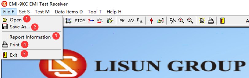
4.2.1 قائمة الملفات
انظر الشكل 4-2.
| رقم الهاتف | ملاحظات |
|---|---|
| ① | افتح ملف EMC |
| ② | احفظ نتائج الاختبار كملف emc. ملاحظة: لا يمكن فتح ملفات emc إلا باستخدام LISUN EMI-9KC البرنامج. |
| ③ | Test Report Options: Enter test report information here |
| ④ | اطبع تقرير |
| ⑤ | الخروج من البرنامج |
4.2.2 قائمة الإعدادات
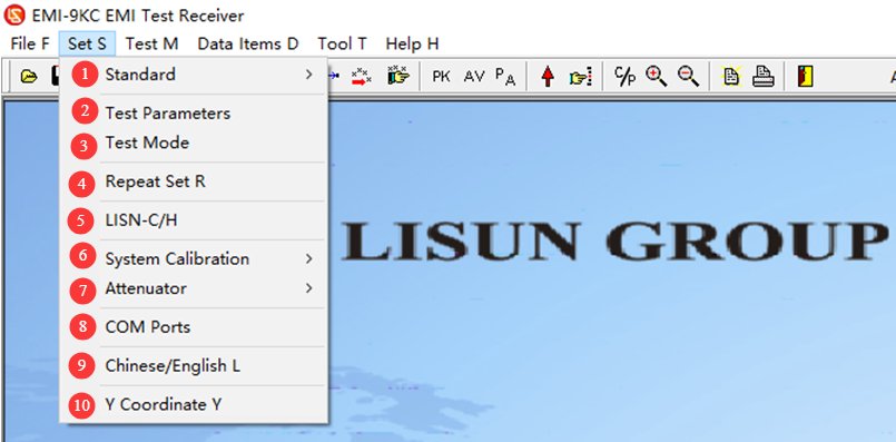
4.2.2.1 القائمة المنسدلة
انظر الشكل 4-3.
| رقم الهاتف | ملاحظات |
|---|---|
| ① | معايير الاختبار: تحديد المعايير أو إضافتها أو تعديلها أو حذفها |
| ② | For test parameters, simply use the default settings; no changes are necessary. If you have specific requirements, you may adjust them as needed. |
| ③ | Test mode; the factory default is automatic mode, so no changes are needed. If you have specific requirements, you can adjust the settings as needed. |
| ④ | Cyclic Sweep Settings |
| ⑤ | Control Artificial Mains Network. Note: This option is available only when selecting standards related to Artificial Mains Network |
| ⑥ | System Calibration: Used by professional engineers when commissioning the equipment; this feature is not required during normal operation of the equipment. |
| ⑦ | Attenuator: The EMI-9KC system does not come with an attenuator as standard equipment; please select “Disable” to proceed. |
| ⑧ | Communication port settings: Once the communication cable is properly connected and the driver is installed, the software will automatically detect the communication port. |
| ⑨ | التبديل بين اللغتين الصينية والإنجليزية |
| ⑩ | Setting the Y-axis coordinate range |
4.2.2.2 خيارات معيار الاختبار
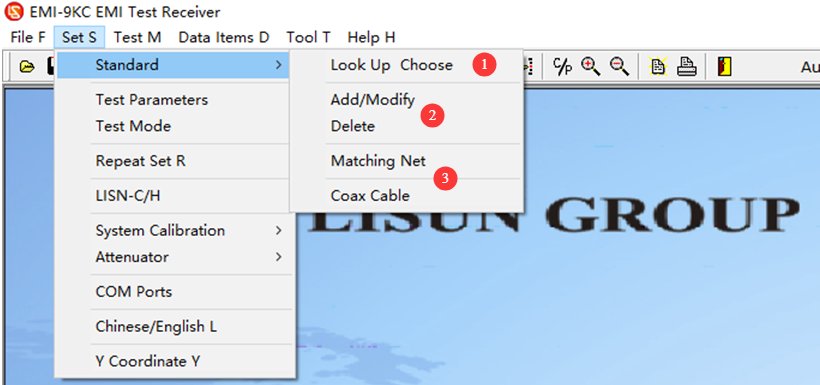
انظر الشكل 4-4.
| رقم الهاتف | ملاحظات |
|---|---|
| ① | معايير الاختيار: يمكنك فقط اختيار المعايير التي تمت إضافتها مسبقًا؛ لا يمكنك تعديل معاييرها. |
| ② | أضف المعايير أو عدّلها أو احذفها. ملاحظة: يُرجى توخي الحذر؛ تُضاف جميع المعايير ومنحنيات الحدود وفقًا للمعايير. إذا كانت لديك بيانات معايير أخرى غير مُدرجة في برنامجنا، فيُرجى إرسال المعايير ذات الصلة إلينا، وسنقوم بإضافتها نيابةً عنك. |
| ③ | Matching networks, coaxial cable corrections. Absorbing Clamp, voltage probes, CDN networks, large-loop antennas, coaxial cables, and other corrections. Note: For use only by LISUN مهندسون محترفون عند تصحيح أخطاء البرامج. |
4.2.2.3 Cyclic Scan Settings
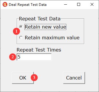
انظر الأشكال من 4 إلى 5.
| رقم الهاتف | ملاحظات |
|---|---|
| ① | You can choose to save the latest value or the maximum value. |
| ② | عدد التكرارات |
| ③ | Once you’ve finished configuring the settings, click OK to save them. |
4.2.2.4 Interface with Artificial Mains Network
انظر الأشكال من 4 إلى 6.
| رقم الهاتف | ملاحظات |
|---|---|
| ① | The factory default setting is manual control, which means you must manually switch between the L and N phases on the LISN-C اللوحة الامامية. |
| After selecting “Program Control,” | ② You can use the software to toggle the L/N switch on the front panel of the LISN-C. |
| ③ During automatic final testing, you can select the current phase or have the system automatically switch between L and N for the final test. |
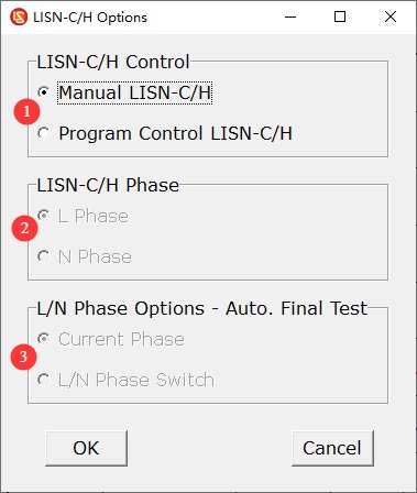
4.2.2.5 Setting the Y-axis Coordinate Range
See Figures 4–7. The default range is 0–130 dB, but you can adjust the setting as needed.
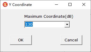
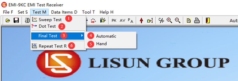
4.2.3 قائمة الاختبار
انظر الأشكال من 4 إلى 8.
| رقم الهاتف | ملاحظات |
|---|---|
| ① | اختبار المسح |
| ② | Spot Test: If you only want to view data for a specific frequency, click here to manually enter the frequency and run the test. |
| ③ | الاختبار النهائي: بعد اكتمال اختبار المسح الضوئي، إذا كنت ترغب في اختبار البيانات المحددة لنقاط معينة مرة أخرى، يمكنك إجراء اختبار نهائي. |
| ④ | الاختبار النهائي التلقائي: يقوم البرنامج تلقائيًا باختيار نقاط التردد التمثيلية بناءً على نتائج الاختبار للاختبار النهائي. |
| ⑤ | Manual Final Test: Users manually add the frequency points to be tested based on their own needs. |
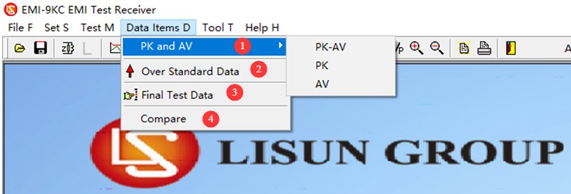
4.2.4 عرض القائمة
انظر الشكل 4-9.
| رقم الهاتف | ملاحظات |
|---|---|
| ① | يُظهر الرسم البياني كلاً من خطوط PK وAV الافتراضية. |
| ② | عرض البيانات التي تقع خارج منحنى الحد |
| ③ | اعرض البيانات الخاصة بنقطة الاختبار النهائية |
| ④ | بعد إجراء اختبارين متتاليين للمسح الضوئي، يمكنك النقر لمقارنة نتائج الاختبارين. |
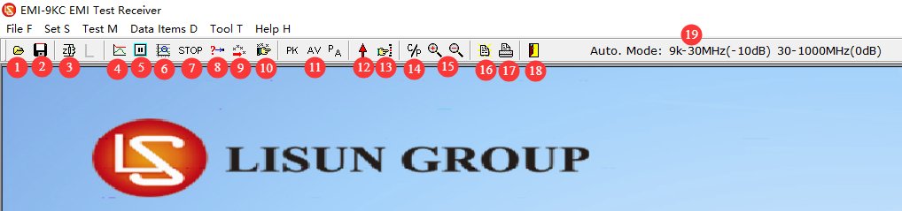
4.2.5 مقدمة إلى اختصارات شريط التنقل
انظر الشكل 4-13.
| رقم الهاتف | ملاحظات |
|---|---|
| ① | افتح ملف EMC |
| ② | احفظ كملف emc |
| ③ | Select this option, then click L/N to automatically toggle the L/N phase switch on the front panel of the LISN-C. Note: This option is available only when standards related to Artificial Mains Network are applied. |
| ④ | اختبار المسح |
| ⑤ | إيقاف الاختبار مؤقتًا |
| ⑥ | Cyclic Scan Test: Click here to perform a cyclic scan test according to the settings in Section 4.2.2.3. |
| ⑦ | توقف عن الاختبار |
| ⑧ | قياس موضعي |
| ⑨ | الاختبار النهائي الآلي |
| ⑩ | الاختبار النهائي اليدوي |
| ⑪ | منحنيات العرض: PK، AV، PK+AV |
| ⑫ | عرض البيانات التي تقع خارج منحنى الحد |
| ⑬ | Display data for the final test point |
| ⑭ | إظهار أو إخفاء نقاط البيانات المتداخلة (إخفاء نقاط البيانات المتداخلة يجعل المنحنى أكثر وضوحًا) |
| ⑮ | تكبير/تصغير: يمكنك تكبير المنحنى لتسهيل رؤيته. بعد النقر، استخدم عجلة زر الفأرة الأوسط في منطقة عرض المنحنى للتكبير أو التصغير. |
| ⑯ | إعدادات تقرير الاختبار |
| ⑰ | اطبع تقرير |
| ⑱ | الخروج من البرنامج |
| ⑲ | يعرض معلمات الوحدات الداخلية للجهاز؛ وهو مخصص للاستخدام من قبل المهندسين المحترفين فقط أثناء تصحيح الأخطاء. |
5. الاستعدادات قبل الاختبار
5.1 Requirements for Setting Up the Test Environment
Standard Procedure (Shielded Chamber): Formal compliance testing must be conducted in a code-compliant Electromagnetic Shielding Cabinet, which completely isolates the test subject from external environmental interference, ensuring the most accurate test results. The LISUN SDR series of Electromagnetic Electromagnetic Shielding Cabinet may be used for this purpose.
Test Setup (Standard Room): If no anechoic chamber is available, select a separate room with an area of at least 15 square meters that contains no other equipment emitting strong electromagnetic interference; the first floor is the optimal location, as it facilitates grounding and results in lower grounding resistance.
يجب أن تكون منطقة الاختبار على بعد 0.8 متر على الأقل من الجدران والأجسام الموصلة الأخرى لمنع انعكاسات الموجات الكهرومغناطيسية من التأثير على نتائج الاختبار.
5.2 Layout Diagram of the Standard Test Environment
5.2.1 Test Setup for Conducted Disturbance Testing of an EUT Using a Single Cable
See Figure 5-1 (taken from CISPR-16-2-1, Figure 11).
| رقم الهاتف | ملاحظات |
|---|---|
| ① | جدار معدني، 2 متر × 2 متر |
| ② | EUT |
| ③ | سلك طاقة طويل للغاية قابل للطي ذهابًا وإيابًا ليصبح قياسه 2 سم × 30 سم |
| ④ | LISN-C شبكة التيار الكهربائي الاصطناعية (AMN) |
| ⑤ | كابل محوري |
| ⑥ | EMI-9KC المتلقي |
| B | راجع نقاط توصيل التأريض واستخدم لوحة تأريض نحاسية لإجراء التوصيل. |
| M | قم بتوصيل LISN-C و EMI-9KC باستخدام محول N-BNC وكابل محوري |
| P | قم بتوصيل سلك الطاقة الخاص بالجهاز بـ LISN-C |
| ينبغي أن تكون التفاوتات المسموح بها في طول الكابل والمسافة قريبة قدر الإمكان من تلك الموجودة في التطبيقات الفعلية. | |
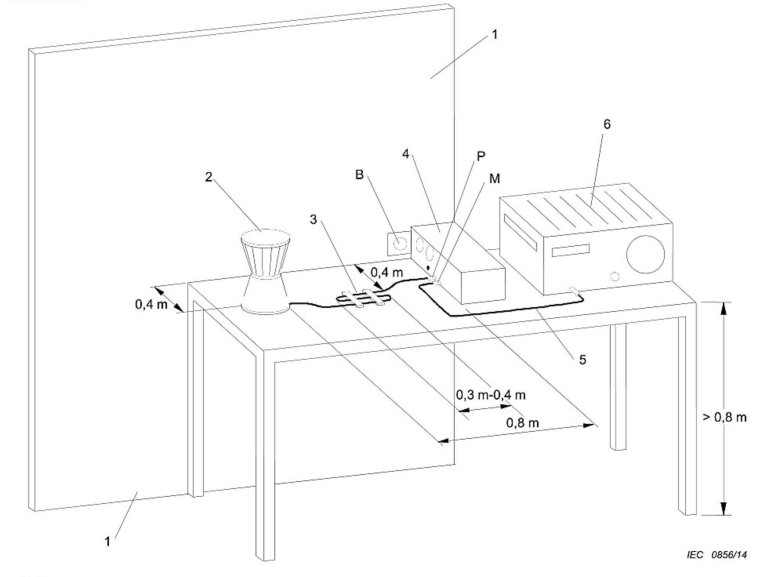
بحسب الظروف المحددة، يمكنك الرجوع إلى مخططات تخطيط الاختبار القياسية الأخرى. فيما يلي النقاط الرئيسية للتخطيط:
Benchtop equipment: Place on an insulated test bench 0.8 m high, with the rear of the equipment 40 cm from a grounded metal plate and ≥80 cm from other conductive objects; fold any excess length of the power cord into an S-shaped bundle 30–40 cm long; do not coil the cord;
Floor-mounted equipment: Place the equipment on an insulating panel (12 mm thick) laid on the floor, with a grounded metal plate measuring at least 2 m × 2 m beneath the insulating panel; keep all sides of the equipment at least 50 cm from the edge of the metal plate and at least 80 cm from the LISN; fold any excess length of the power cord in the center;
منتجات الإضاءة: Lamps with built-in ballasts and separate ballasts shall be placed on insulated supports in accordance with standards; the power cord shall be 0.8 m long and laid out straight; the equipment grounding terminal shall be connected to the reference ground;
Handheld equipment without a ground connection: Wrap metal foil around the grip area to simulate a hand, in accordance with the standard; connect the other end of the simulated hand to the simulated hand interface on the LISN;
5.2.2 Test Setup for Radiated Disturbance Testing of a Single-Cable EUT
انظر الشكل 5-2 (مقتبس من CISPR-16-2-1، الشكل 23).
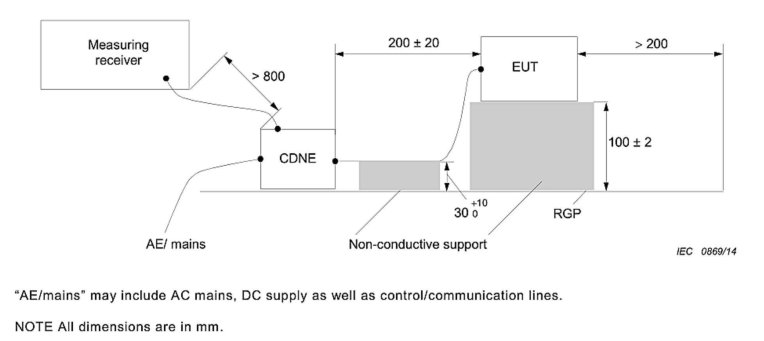
ملاحظة 1: تنطبق طريقة CDNE فقط على الإضاءة والمعدات الكهربائية المماثلة؛ ولا تسمح معايير الأجهزة المنزلية ومعدات تكنولوجيا المعلومات والأدوات الكهربائية (CISPR 14/CISPR 22) باستخدام CDNE كبديل عن غرفة عديمة الصدى أو اختبار المجال المفتوح.
ملاحظة 2: لا يجوز استخدام اختبار الإشعاع البديل لـ CDNE إلا لاختبارات البحث والتطوير الأولية ولا يجوز استخدامه لاختبارات شهادة الامتثال من طرف ثالث.
فيما يلي النقاط الرئيسية للمهمة:
Place an insulated wooden block 10 ± 0.2 cm high on the reference grounding metal plate, and carefully place the equipment under test on top of the block;
The device under test is connected to the CDNE’s EUT port via a power cable 20 ± 10 cm in length; the cable is supported by an insulated spacer 4 ± 0.2 cm high to keep it parallel to the metal plate;
RGP (مستوى الأرض المرجعي) عبارة عن لوحة معدنية مرجعية للتأريض على الأرض؛ يتم وضع وحدة CDNE مباشرة على لوحة التأريض المعدنية لضمان اتصال جيد بين الغلاف واللوحة المعدنية؛
يتم توصيل منفذ AE الخاص بـ CDNE بمصدر الطاقة من مخرج محول العزل؛
Refer to Figure 5-1 for the location of the EMI-9KC وبيئات اختبار أخرى.
5.3 مخطط الأسلاك
انظر الشكل 5-3.
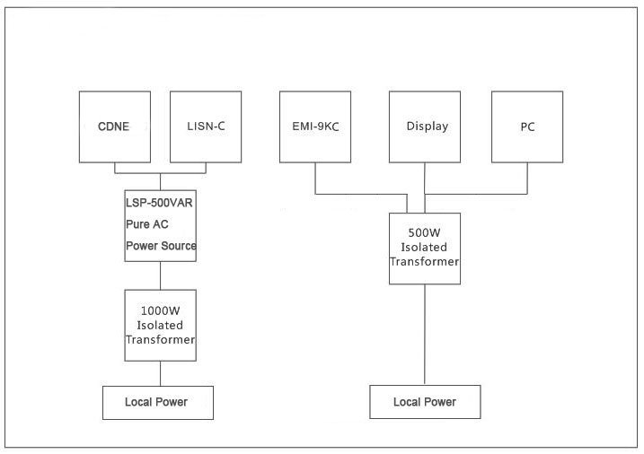
ملاحظة: تتكون سلسلة LSP من LISUN pure sine wave regulated power supplies, designed to provide a stable, pure sine wave AC power supply to the EUT; these are available for optional purchase.
6. إجراءات اختبار المناعة الموصلة والمشعة
6.1 استعدادات
راجع الفصلين 3 و 5 لإعداد بيئة الاختبار وتوصيل جميع معدات النظام وجهاز الاختبار.
6.2 Warm-up at Startup
Refer to Section 2.2.1. Power on all equipment and the EUT in the correct sequence and following the proper procedures, ensuring that the EUT is in its normal operating state. As required by the standard, the EUT must be allowed to warm up to a stable operating state (typically 15 to 30 minutes) before testing.
6.3 Confirmation of Test Parameters
6.3.1 اختيار المعايير
اختر المعيار المناسب. على سبيل المثال، إذا كنت تستخدم LISN-C to test for conducted emissions, select EN 55015; if you are using the CDNE-M316 to test for radiated emissions, select EN 55015 CDNE-M3.
6.3.2 إعدادات المخفف
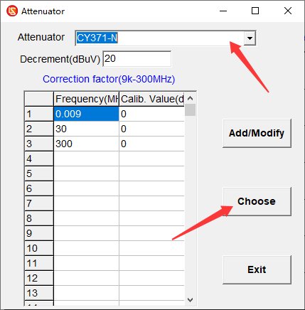
استخدم EMI-9KC does not come with an attenuator as standard; simply select the option to disable the attenuator. If you purchase and use an external attenuator, you must select the correct attenuator parameters; see Figure 6-1 for the settings.
6.4 اختبار المسح
6.4.1 تبديل طور الخط/المحايد في LISN-C
Both the L phase and the N phase must undergo conducted emission testing. After testing one phase, you can switch the LISN-C’s L/N phase switch manually or via software to test the other phase. Note: Do not switch the L/N phase switch during testing.
6.4.2 واجهة اليد الاصطناعية الخاصة بـ LISN-C
When testing Class I and Class II ungrounded handheld power tools (handheld drills, angle grinders, electric saws, grinders, etc.), ungrounded handheld small household appliances (handheld hair dryers, handheld vacuum cleaners, handheld food processors, etc.), and handheld medical electrical equipment (dental handpieces, handheld physical therapy devices, in accordance with IEC 60601-1-2), this must be used.
Copper wire and 0.05 mm thick copper foil must be used to connect the LISN-CARTIFICIAL HAND interface to the EUT handle and housing in order to apply human body simulation coupling.
6.4.3 اختبار المسح العام
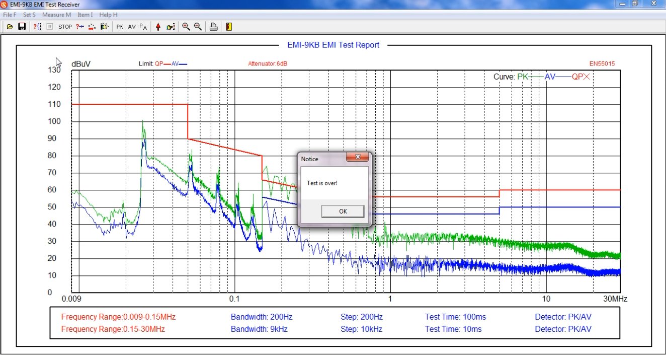
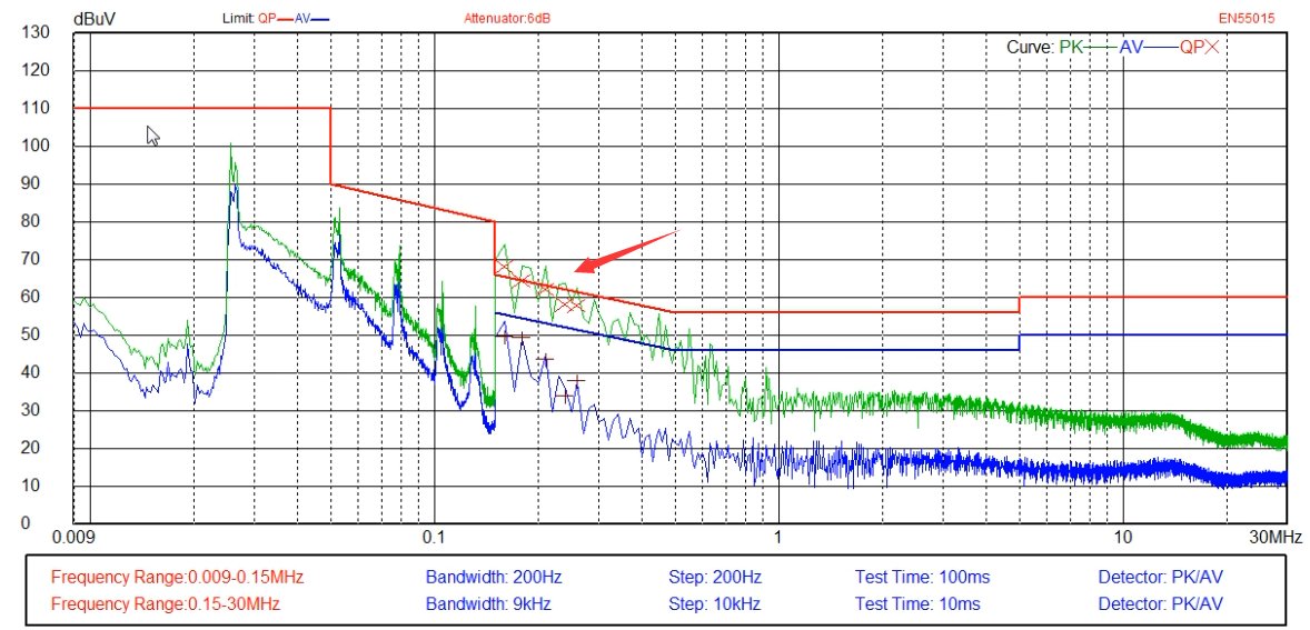
Click “Scan Test” (or “Loop Scan Test”), wait for the scan to complete. If an error occurs, click “Stop Test,” make the necessary adjustments, and then restart the test. Once the scan is complete, see Figure 6-2.
الخط الأحمر: خط حد شبه الذروة (QP)؛
الخط الأزرق: خط الحد المتوسط (AV)؛
المنحنى الأخضر: منحنى اختبار الذروة (PK)؛
المنحنى الأزرق: منحنى الاختبار المتوسط (AV).
6.5 إمتحان نهائي
If the average values (AV) of the test results are all below the limit curve, and the peak values (PK) are all below the quasi-peak (QP) limit curve, then the EUT meets the standard requirements, because the actual quasi-peak (QP) value measured during testing will not exceed the peak (PK) value. If the tested peak value (PK) exceeds the quasi-peak (QP) limit curve, the EUT is not necessarily non-compliant with the standard; a final test is required.
6.5.1 الاختبار النهائي التلقائي
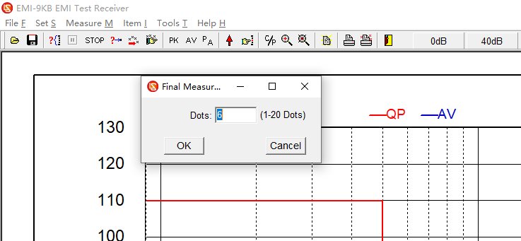
أدخل عدد نقاط التردد المراد اختبارها، وسيقوم البرنامج تلقائيًا بتحديد نقاط التردد بناءً على منحنى الاختبار لإجراء الاختبار النهائي، كما هو موضح في الشكل 6-3.
6.5.2 الاختبار النهائي اليدوي
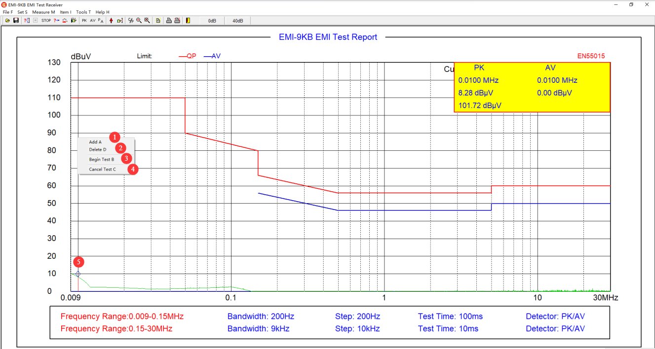
في منطقة منحنى اختبار البرمجيات، انقر بزر الماوس الأيمن على النقطة التي سيتم إجراء الاختبار النهائي عندها، كما هو موضح في الشكل 6-4.
| رقم الهاتف | ملاحظات |
|---|---|
| ① | إضافة نقطة نهاية |
| ② | حذف نقطة النهاية |
| ③ | بعد إضافة جميع نقاط الاختبار النهائي المطلوبة، انقر فوق "بدء الاختبار النهائي". |
| ④ | إذا لم تعد ترغب في المشاركة في الاختبار النهائي، فانقر فوق "إلغاء الاختبار النهائي". |
| ⑤ | تشير المعينات الزرقاء إلى مواقع نقاط الاختبار النهائية المضافة. |
6.5.3 تفسير بيانات الاختبار النهائي
See Figure 6-5. The red X marks the quasi-peak (QP) values from the final test. If all quasi-peak (QP) values from the final test fall below the quasi-peak (QP) limit curve, the EUT meets the standard requirements. Otherwise, it does not meet the standard requirements.
6.6 قياس النقاط
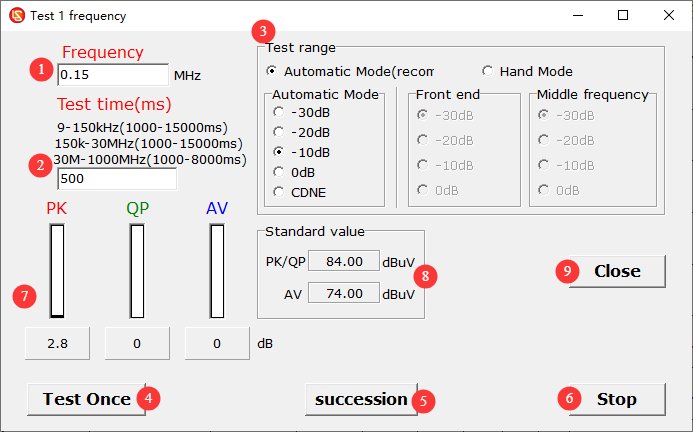
انظر الشكل 6-6.
| رقم الهاتف | ملاحظات |
|---|---|
| ① | Enter the frequency points you want to test |
| ② | Test duration: You can set it according to the prompts. |
| ③ | Test range: Unless otherwise specified, simply select “Auto” mode. |
| ④ | Perform a single test |
| ⑤ | Conduct continuous testing |
| ⑥ | توقف عن الاختبار |
| ⑦ | Display test results: PK, QP, and AV values |
| ⑧ | Displays the limit value for that frequency point under the currently selected standard. |
| ⑨ | Close the Point Measurement Interface |
6.6 Save and Print the Test Report
راجع القسم 4.2.1 لحفظ أو طباعة تقرير الاختبار.
6.7 Procedure for Shutting Down the System at the End of a Test
Ensure the equipment is in the “Test Stop” state → Disconnect the coaxial cable on the LISN/CDNE side → Turn off the EUT’s power → Turn off the receiver and computer → Turn off Isolation Transformer.
7. الصيانة اليومية للمعدات والعناية بها
7.1 Routine Use and Maintenance
7.1.1 صيانة الهيكل الخارجي والواجهات
After each use, wipe the surface of the equipment with a dry, soft cloth to remove dust. Do not use highly corrosive organic solvents such as gasoline, acetone, or thinners. To clean stubborn stains, use a lint-free cloth dipped in a small amount of anhydrous ethanol to wipe the area quickly, then dry it immediately afterward.
Inspect the BNC connectors, power connectors, and terminal blocks monthly; remove any oxidation to ensure good contact; and cover the connectors with protective caps when not in use to prevent dust from entering.
Each piece of equipment is assigned to a specific user; unauthorized personnel are prohibited from operating it. Do not disassemble the equipment casing without the manufacturer’s authorization; any hardware damage resulting from unauthorized disassembly is not covered under the free warranty.
7.1.2 صيانة الكابلات والملحقات
تجنب ثني الكابلات المحورية بشدة، أو الدوس عليها، أو تعريضها لضغط الأجسام الثقيلة. عند تخزينها، لفها بشكل غير محكم لمنع الموصلات الداخلية من الانقطاع.
تعامل مع الملحقات الدقيقة مثل المخففات والموصلات بحرص لمنع حدوث تلف داخلي ناتج عن سقوطها.
يجب عدم تعديل إعدادات البرنامج بشكل تعسفي، ويجب عدم تغيير المعايير المدمجة وبيانات المعايرة دون إذن.
7.2 مواصفات التخزين
7.2.1 متطلبات بيئة التخزين
Temperature: 5°C to 35°C; relative humidity: ≤65% RH; dry, dust-free environment free of corrosive gases.
7.2.2 عمليات التخزين طويلة الأجل
قم بإيقاف تشغيل الطاقة وافصل جميع الكابلات؛ نظف الجهاز وقم بتغليفه بغشاء مقاوم للغبار؛ قم بتشغيل الطاقة لمدة 30 دقيقة كل شهر لمنع تلف المكونات بسبب الرطوبة.
7.3 متطلبات فترة المعايرة
لضمان دقة القياس وموثوقية تشغيل الجهاز، يُوصى بإرساله دوريًا إلى مختبر قياسات معتمد تابع لجهة خارجية لإجراء المعايرة. يُوصى بإجراء المعايرة كل 12 شهرًا. ويمكن للمستخدمين تحديد فترة المعايرة المناسبة بناءً على وتيرة الاستخدام والظروف البيئية ومتطلبات نظام الجودة.
8. استكشاف الأخطاء وإصلاحها وحل المشكلات الشائعة
| أعراض الخلل | العملية |
|---|---|
| قد تظهر رسائل خطأ متنوعة أثناء استخدام البرنامج، مثل فشل البرنامج في الفتح أو حدوث أخطاء أثناء المسح الضوئي. | تأكد من تسجيل دخولك إلى جهاز الكمبيوتر الخاص بك باستخدام حساب مسؤول، وتأكد من تشغيل البرنامج بصلاحيات المسؤول. |
| The software worked normally during the scan test, but froze during the final test. | يتطلب الاختبار النهائي متطلبات اتصال أكثر صرامة من اختبار المسح. يُرجى التأكد من استخدام كابل الاتصال الأصلي الخاص بنا فقط، وعدم استخدام أي كابلات اتصال أو أسلاك تمديد أخرى. يُرجى التأكد من استخدام منفذ الاتصال الموجود في الجزء الخلفي من جهاز الكمبيوتر المكتبي (عادةً لا توفر منافذ USB في أجهزة الكمبيوتر المحمولة وتلك الموجودة في الجزء الأمامي من أجهزة الكمبيوتر المكتبية طاقة كافية، مما قد يؤثر على الاتصال). إذا استمرت المشكلة، يُرجى محاولة إضافة... RS232 communication port to your computer and use only an RS232 communication cable—do not use an RS232-to-USB adapter for communication |
| تكون نتائج الاختبارات عموماً أقل أو أعلى من المتوقع. | يرجى التحقق من أن إعدادات مخفف الإشارة البرمجية تتطابق مع الظروف الفعلية. |
| تكون نتائج الاختبار قريبة دائمًا من مستوى الضوضاء الخلفية، ولا يستطيع جهاز استقبال التداخل الكهرومغناطيسي اكتشاف أي إشارات. | تحقق من توصيل الكابل المحوري؛ استبدل الكابل المحوري وحاول مرة أخرى. |
| ضوضاء خلفية عالية للغاية وتقلبات كبيرة في بيانات الاختبار | Verify that all equipment in the system uses Isolation Transformer; optimize the grounding system to reduce grounding resistance; turn off other electrical equipment in the laboratory or conduct testing inside a shielded room. |