
 الإنجليزية
 中文简体
中文简体 Русский
 Español
 Português
 Türkçe
 العربية
 Deutsch
 Polski
 Italiano
 Français
 한국어
한국어 ไทย
ไทย Tiếng Việt
 日本語
日本語





























مولد مناعة السيارات ضد العابر
مستخدم المالكين
قابل للتطبيق LISUN الموديلات: EMS-ISO7637-P123-80V100A、EMS-ISO7637-P123-80V30A、EMS-ISO7637-P123-80V50A、EMS-ISO7637-P1235-80V100A、EMS-ISO7637-P1235-80V30A、EMS-ISO7637-P1235-80V50A、EMS-ISO7637-P5-80V100A、EMS-ISO7637-P5-80V30A、EMS-ISO7637-P5-80V50A
1. فهم أساسي للمعدات
1.1 تصنيف النموذج
| LISUN الموديل | EMS-ISO7637-P1235-80V30A | EMS-ISO7637-P123-80V30A | EMS-ISO7637-P5-80V30A |
|---|---|---|---|
| اسم المنتج | مولد مناعة السيارات ضد العابر | Automotive Electronic Load Dump Simulator | |
| الجهد والتيار للجهاز قيد الاختبار | Built-in Coupling Decoupling Network: 80 V/30 A (optional: 80 V/50 A and 80 V/100 A) | ||
| نظام التحكم | 10.1-inch Chinese-English Android Capacitive Touchscreen Display + Supports Remote Control via PC Software | ||
| أشكال الموجات الاختبارية | Pulse 1, Pulse 2a, Pulse 3a, Pulse 3b, Pulse 5a, Pulse 5b | Pulse 1, Pulse 2a, Pulse 3a, Pulse 3b | Pulse 5a, Pulse 5b |
| خدمات أخرى | Supports immunity testing for 12V/24V automotive electronic systems; features built-in standard test parameters that can be accessed with a single click, and supports user-defined parameters | ||
1.2 المعايير المعمول بها
| رقم قياسي | الاسم |
|---|---|
| إسو شنومكس-شنومكس: شنومكس | Road Vehicles—Electrical Disturbances from Conduction and Coupling—Part 2: Electrical Transients Conduced Along Supply Lines Only |
| إسو شنومكس-شنومكس: شنومكس | Road Vehicles—Electrical Disturbances from Conduction and Coupling—Part 3: Electrical Transient Transmission by Capacitive and Inductive Coupling via Lines Other Than Supply Lines |
| إسو شنومكس-شنومكس: شنومكس | Road Vehicles—Environmental Conditions and Testing for Electrical and Electronic Equipment—Part 2: Electrical Loads |
1.3 سيناريوهات التطبيق
استخدم EMS-ISO7637 Automotive Transient Immunity Generator (also known as the Automotive Electronic Immunity Test System) is a professional test instrument independently developed by LISUN. It is designed to simulate various typical electromagnetic disturbances generated during normal vehicle operation, as well as changes in the vehicle’s onboard power supply that occur during vehicle startup, the switching of electronic devices, and battery charging and discharging. The waveforms generated by the equipment comply with the ISO 7637 series of international standards and meet the requirements of most automotive manufacturers for in-vehicle electronic immunity testing.
Applications include: conducted immunity testing of electronic components such as automotive ECUs, sensors, and controllers; verification of electromagnetic compatibility (EMC) performance for automotive components prior to shipment; validation and optimization of circuit protection solutions during the R& D phase; and compliance testing by third-party testing laboratories.
2. احتياطات الاستخدام
2.1 متطلبات البيئية
Ambient temperature: 23 °C ± 5 °C; relative humidity: 45–75%, non-condensing; altitude: ≤2000 m; no strong vibrations or electromagnetic interference in the surrounding area; use of the equipment in dusty or flammable and explosive environments is strictly prohibited.
2.2 متطلبات امدادات الطاقة
Input power supply: AC 220 V ±10%, 50 Hz; Input power: ≤1 kW; The power supply must be reliably grounded, with a grounding resistance of ≤1 Ω; It is recommended to use a voltage-stabilized power supply to prevent power grid fluctuations from affecting test accuracy.
2.3 مبادئ الأسلاك
Use power cables with the specified wire gauge to prevent overheating under high current conditions; keep test cables as short as possible and route them in parallel to minimize the impact of parasitic parameters; ensure that the DUT (Device Under Test) enclosure is reliably connected to the equipment’s protective ground; and route signal and power cables separately to avoid cross-interference.
2.4 إرشادات السلامة التشغيلية
Wear insulated protective gear; before testing, ensure all connections are secure and that there are no exposed conductors; do not plug in or unplug test cables during testing to avoid arc burns; do not touch the DUT or test fixtures while the pulse is being output; if you hear unusual noises, smell an unusual odor, or see smoke, immediately disconnect the power; During prolonged continuous testing, ensure the equipment is properly ventilated for heat dissipation.
3. نظرة عامة على المعدات والأسلاك
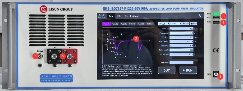
3.1 اللوحة الامامية
انظر الشكل 3-1.
| رقم الهاتف | ملاحظات |
|---|---|
| ① | Device power switch: Press briefly to turn on; press and hold to turn off. |
| ② | شاشة لمس سعوية ٤.٧ بوصة |
| ③ | USB1 port: Used by LISUN engineers for device debugging; users do not need to use it. |
| ④ | USB 2.0 port, which can be used to connect a mouse to control the touchscreen, or to connect a USB flash drive to upgrade the software or update database files |
| ⑤ | BNC coaxial connector, used to connect auxiliary devices such as ICC, DCC, CCC (if any), or to connect an external oscilloscope to view BNC-coupled waveforms |
| ⑥ | DUT power cable connector, used to connect the DUT; observe the polarity |
3.2 لوحة الظهر
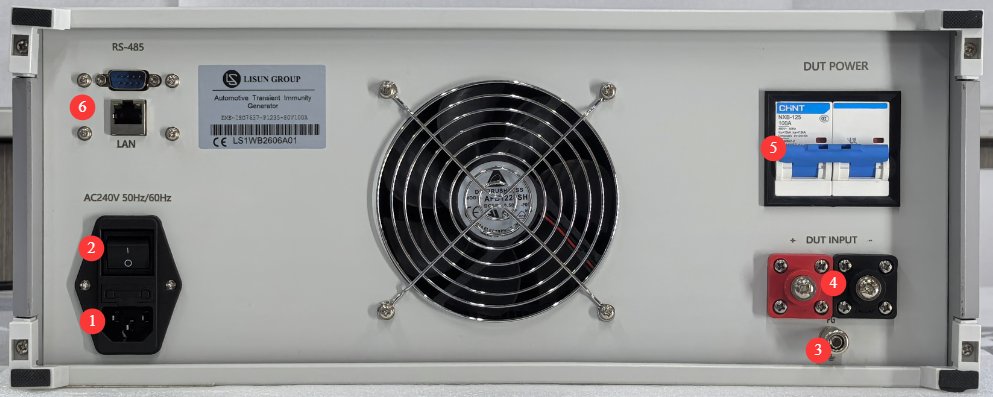
انظر الشكل 3-2.
| رقم الهاتف | ملاحظات |
|---|---|
| ① | Power cord receptacle and fuse; ensure the input power supply is properly grounded |
| ② | Circuit breaker, main input power supply switch for the equipment |
| ③ | Protective grounding terminal: If the input power supply does not have a reliable ground connection, a separate ground wire must be used to connect it to the ground. |
| ④ | DUT Power Input Connector: A suitable external power supply must be provided for the DUT. You may use LISUN’s LIS-APS series four-quadrant power supply, or another suitable DC regulated power supply appropriate for the DUT. Pay attention to polarity. |
| ⑤ | DUT Power Switch |
| ⑥ | RS485 interface/LAN port, which can be connected to a computer to use the host software (for backup purposes). The host software offers the same functionality as the touchscreen; please contact us if needed. |
3.3 Introduction to Accessories
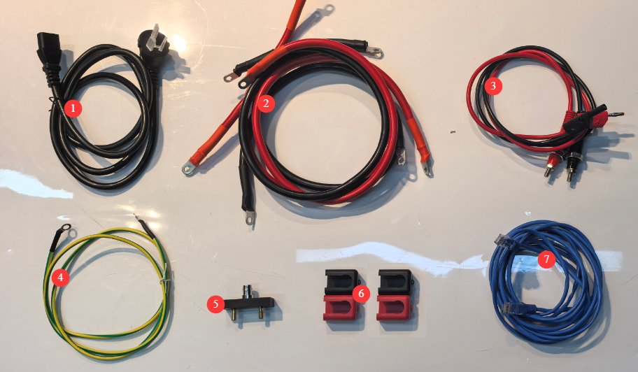
انظر الشكل 3-3.
| رقم الهاتف | ملاحظات |
|---|---|
| ① | السلطة الحبل |
| ② | DUT Power Supply Input and Output Cables |
| ③ | The slim-profile output cable can be used to connect to LISUN’s calibration resistor, the LIS-CAR. |
| ④ | سلك ارضي |
| ⑤ | BNC adapter, used to connect to an external oscilloscope to view power line-coupled waveforms; be sure to observe the correct polarity when using it. |
| ⑥ | Insulation Protective Covers for DUT Input and Output Power Cables |
| ⑦ | Ethernet cable, used to connect a computer for use with host software |
4. مقدمة لبرنامج الشاشة اللمسية
4.1 واجهة الاختبار
4.1.1 The Pulse 1 Interface
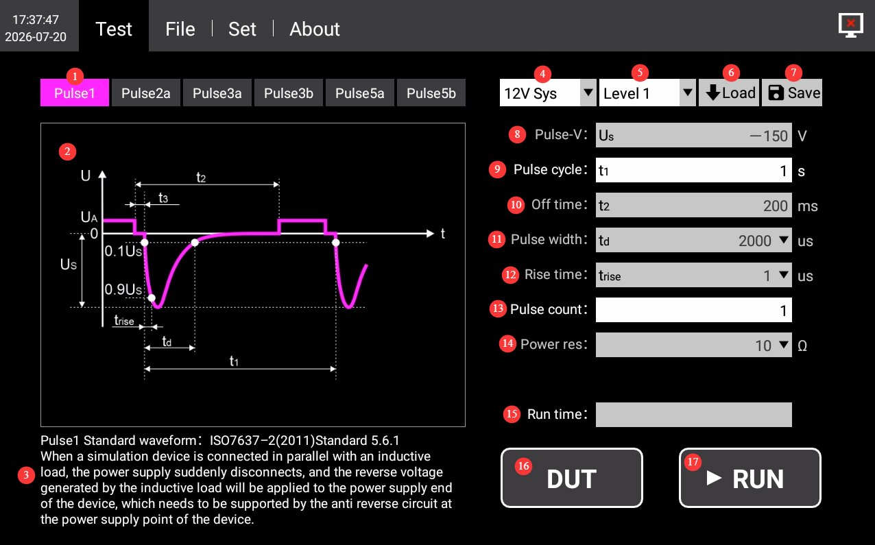
انظر الشكل 4-1.
| رقم الهاتف | ملاحظات |
|---|---|
| ① | Waveform Selection: Click to select “Pulse 1” |
| ② | Schematic Diagram of Pulse 1 Waveform |
| ③ | Pulse 1 Standard Source and Test Instructions |
| ④ | Electrical System: Optional built-in 12V/24V system waveform parameters; custom parameters are also available. |
| ⑤ | Severity Levels: Select the appropriate severity level for each waveform as specified in the standard, as needed. |
| ⑥ | Load the test parameters saved by the device; this is generally not necessary. If you have previously customized parameters, you can load them. |
| ⑦ | Save the current test parameters. If you have custom parameters, you can click to save the current custom parameters to the device. You can manage them in the Files interface. |
| ⑧ | Pulse voltage: The built-in system waveform parameters have been set according to the standard and cannot be modified. When configuring custom parameters, you can set the pulse peak voltage Us. |
| ⑨ | Pulse Period: You can set the period of a single pulse; unless otherwise specified, use the default value. |
| ⑩ | Power-off time: the duration for which power to the 12V/24V system is disconnected. The built-in system waveform parameters have been set according to the standard and cannot be modified. These parameters can be set when configuring custom settings. |
| ⑪ | Pulse width: The built-in system waveform parameters are set according to the standard and cannot be modified. When configuring custom parameters, you can select the width of a single pulse from among 9 options ranging from 50 us to 2 ms. |
| ⑫ | For the rise time, the built-in system waveform parameters have been set according to the standard and cannot be modified. When configuring custom parameters, you can select the rise time for Pulse 1 from the options 1 us or 3 us. |
| ⑬ | Number of Pulses: Sets the number of pulses to be output during this operation. Unless otherwise specified, use the default value. |
| ⑭ | Power supply internal resistance: The built-in system waveform parameters have been set according to the standard and cannot be modified. When configuring custom parameters, you can select the internal resistance of the pulse source from the following options: 2 Ω, 4 Ω, 10 Ω, 30 Ω, 50 Ω, 60 Ω, and 100 Ω. |
| ⑮ | Runtime is displayed and calculated automatically; a progress bar will appear to show the test progress once the test begins. |
| ⑯ | DUT: Click to turn on the DUT power; click again to turn it off. |
| ⑰ | RUN: Once you have selected the waveform and other parameters, click this button to start the test. During the test, the progress bar updates once per second to show the current progress until the test is complete. Click this button again during the test to stop the current test. |
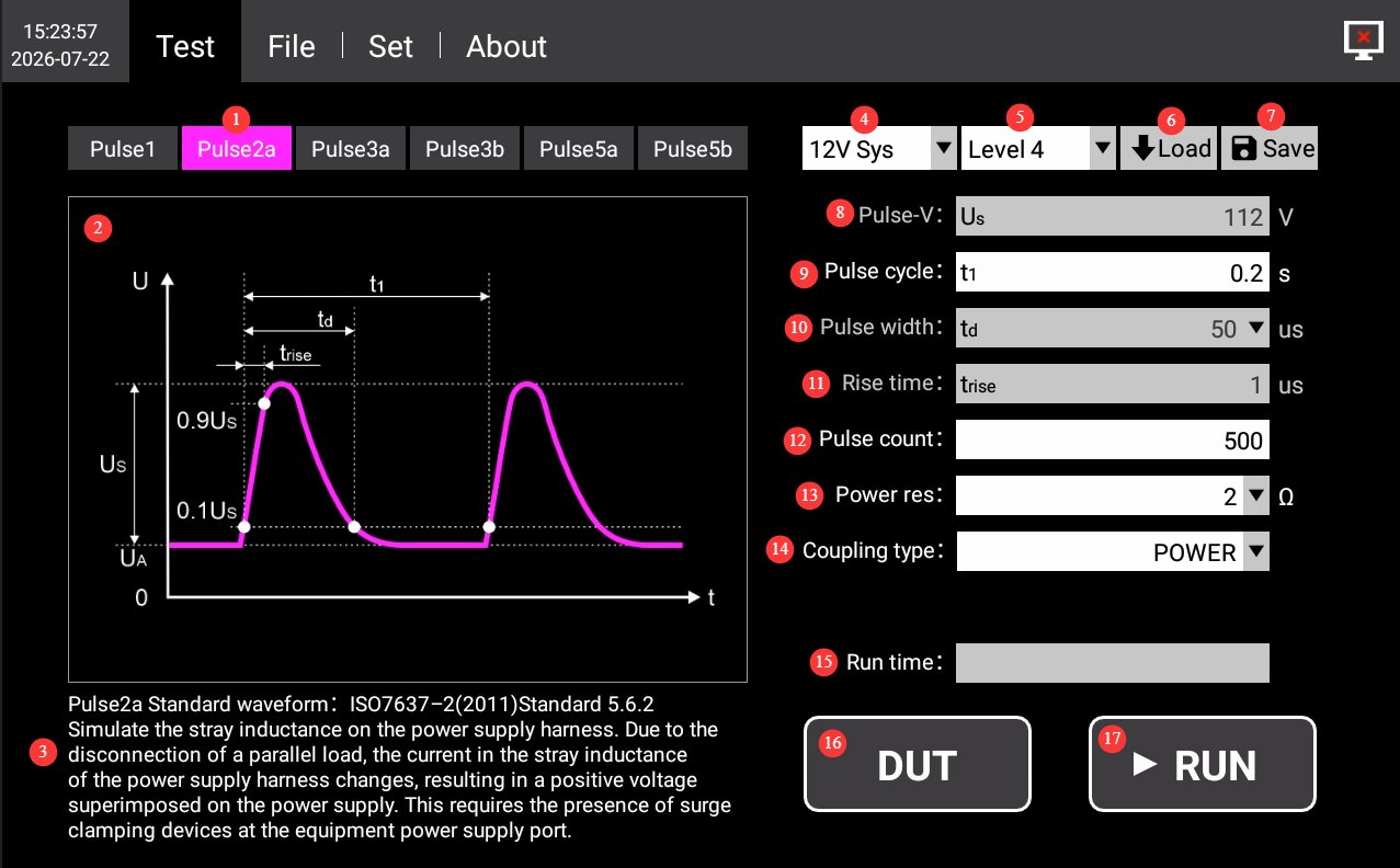
4.1.2 Pulse 2a Interface
انظر الشكل 4-2.
| رقم الهاتف | ملاحظات |
|---|---|
| ① | Waveform Selection: Click to select Pulse 2a |
| ② | Pulse 2a Waveform Diagram |
| ③ | Pulse 2a Reference Sources and Test Instructions |
| ④ | Electrical System: Optional built-in 12V/24V system waveform parameters; custom parameters are also available. |
| ⑤ | Severity Levels: Select the appropriate severity level for each waveform as specified in the standard, as needed. |
| ⑥ | Load the test parameters saved by the device; this is generally not necessary. If you have previously customized parameters, you can load them. |
| ⑦ | Save the current test parameters. If you have custom parameters, you can click to save them to the device. You can manage them in the Files interface. |
| ⑧ | Pulse voltage: The built-in system waveform parameters have been set according to the standard and cannot be modified. When configuring custom parameters, you can set the pulse peak voltage Us. |
| ⑨ | Pulse Period: You can set the period for a single pulse; unless otherwise specified, use the default value. |
| ⑩ | Pulse width: The built-in system waveform parameters are preconfigured according to the standard and cannot be modified. When configuring custom parameters, you can select the width of a single pulse from among 9 options ranging from 50 us to 2 ms. |
| ⑪ | For the rise time, the built-in system waveform parameters have been set according to the standard and cannot be modified. When configuring custom parameters, you can set the pulse rise time. |
| ⑫ | Number of Pulses: Set the number of pulses to be output during this operation. Unless otherwise specified, use the default value. |
| ⑬ | The power supply’s internal resistance and the built-in system waveform parameters have been set according to the standard and cannot be modified. The power supply’s internal resistance can be modified when configuring custom parameters. |
| ⑭ | Coupling methods: Choose between power line output or BNC coaxial connector output. The coaxial output supports ICC (requires LISUN’s LIS-BCP110 ICC Current Injection Probe and LIS-CCF500 ICC High-Current Injection Probe) and DCC (requires LISUN’s DCC-100 DCC Coupling Capacitor). |
| ⑮ | Runtime is displayed and calculated automatically; a progress bar will appear to show the test progress once the test begins. |
| ⑯ | DUT: Click to turn on the DUT power; click again to turn it off. |
| ⑰ | RUN: Once you have selected the waveform and other parameters, click this button to start the test. During the test, the progress bar updates once per second to show the current progress until the test is complete. Click this button again during the test to stop the current test. |
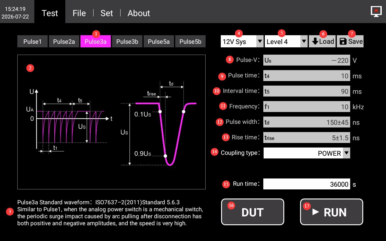
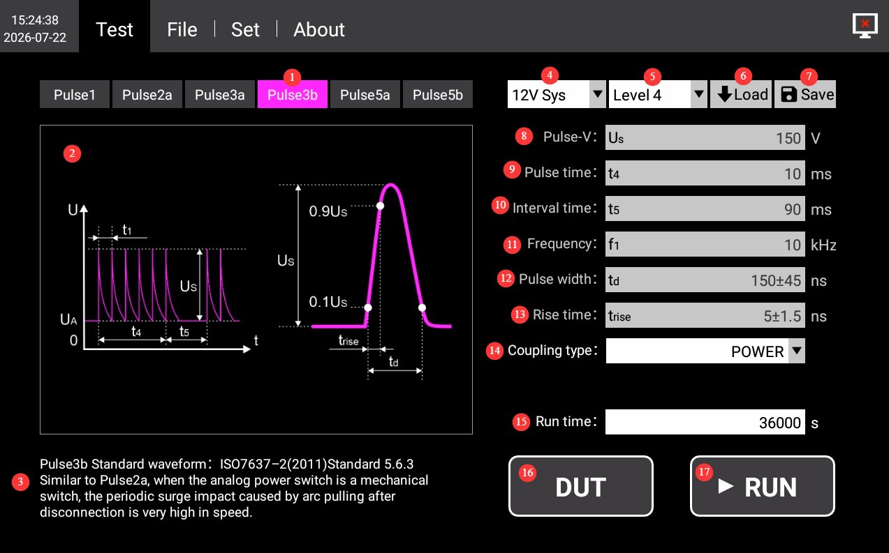
4.1.3 Pulse 3a/3b Interface
انظر الشكلين 4-3 و 4-4.
| رقم الهاتف | ملاحظات |
|---|---|
| ① | Waveform Selection: Click to select Pulse 3a/3b |
| ② | Schematic Diagram of Pulse 3a/3b Waveforms |
| ③ | Pulse 3a/3b Standards Sources and Test Instructions |
| ④ | Electrical System: Optional built-in 12V/24V system waveform parameters; custom parameters are also available. |
| ⑤ | Severity Levels: Select the appropriate severity level for each waveform as specified in the standard, as needed. |
| ⑥ | Load the test parameters saved by the device; this is generally not necessary. If you have previously customized parameters, you can retrieve them. |
| ⑦ | Save the current test parameters. If you have custom parameters, you can click to save them to the device. You can manage them in the Files interface. |
| ⑧ | Pulse voltage: The built-in system waveform parameters have been set according to the standard and cannot be modified. When configuring custom parameters, you can set the pulse peak voltage Us. |
| ⑨ | Pulse duration: The built-in system waveform parameters are already set according to the standard and cannot be modified. When configuring custom parameters, you can set the duration of the pulse group. |
| ⑩ | Interval Time: The built-in system waveform parameters have been set according to the standard and cannot be modified. When configuring custom parameters, you can set the interval time between pulse groups. |
| ⑪ | Pulse frequency: The built-in system waveform parameters are already set according to the standard and cannot be modified. When configuring custom parameters, you can set the frequency of the output pulses within a pulse group. |
| ⑫ | Pulse width: The built-in system waveform parameters are already set according to the standard and cannot be modified. When configuring custom parameters, you can set the pulse group width. |
| ⑬ | For the rise time, the built-in system waveform parameters have been set according to the standard and cannot be modified. The pulse rise time can be set when configuring custom parameters. |
| ⑭ | Coupling methods: You can choose between power cord output or BNC coaxial connector output. The coaxial output supports two coupling methods: CCC (requires LISUNالصورة VFTC capacitive coupling clamp) and DCC (requires LISUN’s DCC-100 DCC coupling capacitor). |
| ⑮ | Runtime: Configurable; the standard minimum test duration is 3600 seconds. |
| ⑯ | DUT: Click to turn on the DUT’s power; click again to turn it off. |
| ⑰ | RUN: Once you have selected the waveform and other parameters, click this button to start the test. During the test, the progress bar updates once per second to show the current progress until the test is complete. Click this button again during the test to stop the current test. |
4.1.4 Pulse 5a/5b Interface
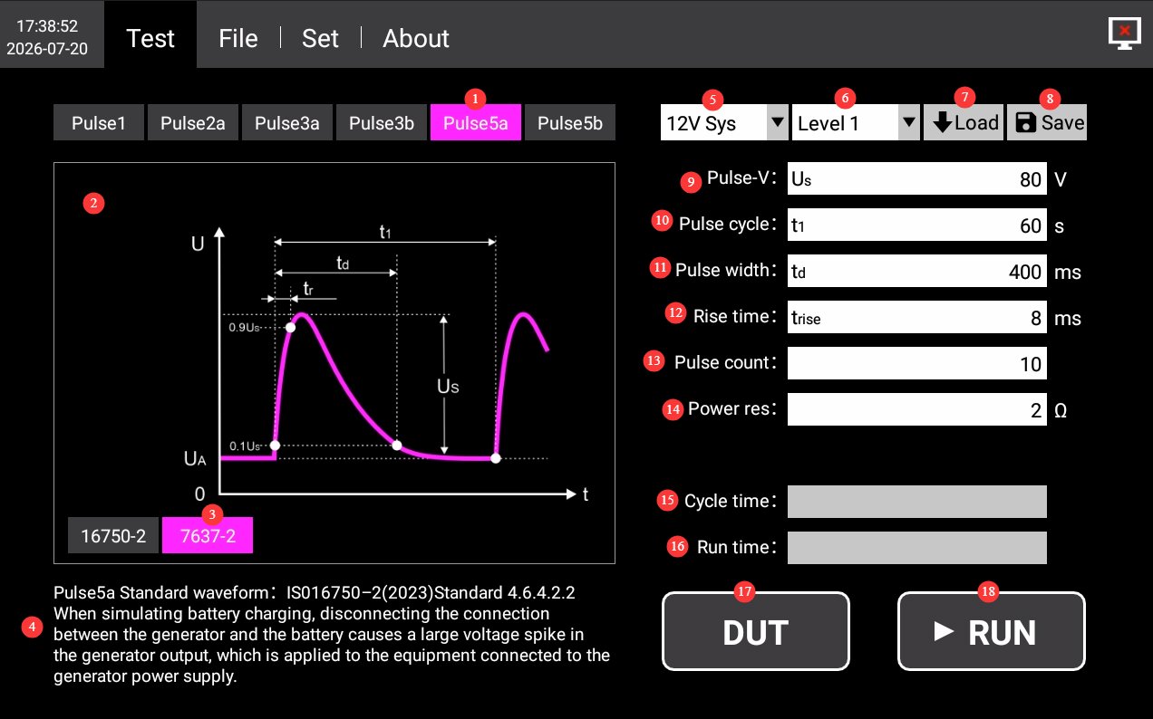
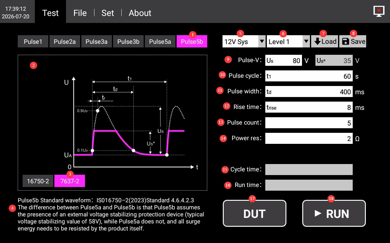
4.1.4.1 ISO 7637-2
انظر الشكلين 4-5 و 4-6.
| رقم الهاتف | ملاحظات |
|---|---|
| ① | Waveform Selection: Click to select Pulse 5a/5b |
| ② | Schematic Diagram of Pulse 5a/5b Waveforms |
| ③ | Select the ISO 7637-2 standard |
| ④ | Pulse 5a/5b Standard Sources and Test Instructions |
| ⑤ | Electrical System: Optional built-in 12V/24V system waveform parameters; custom parameters are also available. |
| ⑥ | Severity Levels: Select the appropriate severity level for each waveform as specified in the standard, as needed. |
| ⑦ | Load the test parameters saved by the device; this is generally not necessary. If you have previously customized parameters, you can load them. |
| ⑧ | Save the current test parameters. If you have custom parameters, you can click to save them to the device. You can manage them in the Files interface. |
| ⑨ | Pulse Voltage: You can set the pulse peak voltage (Us) for Pulse 5a and the pulse clamping voltage (Us*) for Pulse 5b. Unless otherwise specified, use the default values. |
| ⑩ | Pulse Period: You can set the period for a single pulse. Unless otherwise specified, use the default value. |
| ⑪ | Pulse width: You can set the width of a single pulse; unless otherwise specified, use the default value. |
| ⑫ | Rise Time: You can set the rise time of the pulse. Unless otherwise specified, use the default value. |
| ⑬ | Number of Pulses: You can set the number of pulses to be output during this operation. Unless otherwise specified, use the default value. |
| ⑭ | Power Supply Internal Resistance: The internal resistance of the pulse source can be set within a range of 0.5 Ω to 40 Ω, with a resolution of 0.1. Unless otherwise specified, use the default value. |
| ⑮ | Current Cycle Duration Display |
| ⑯ | Total Runtime Display |
| ⑰ | DUT: Click to turn on the DUT power; click again to turn it off. |
| ⑱ | RUN: Once you have selected the waveform and other parameters, click this button to start the test. During the test, the progress bar updates once per second to show the current progress until the test is complete. Clicking this button again during the test will stop the current test. |
4.1.4.2 ISO 76750-2
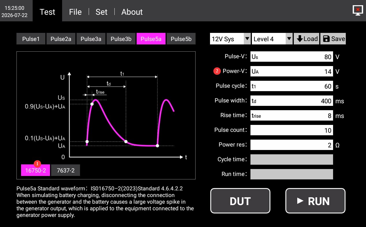
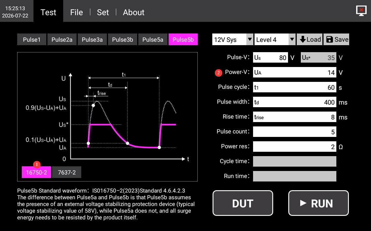
انظر الشكلين 4-7 و 4-8.
| رقم الهاتف | ملاحظات |
|---|---|
| ① | Select the ISO 16750-2 standard |
| ② | The DUT’s supply voltage must be entered; all other requirements are consistent with ISO 7637-2. |
4.2 Database File Interface
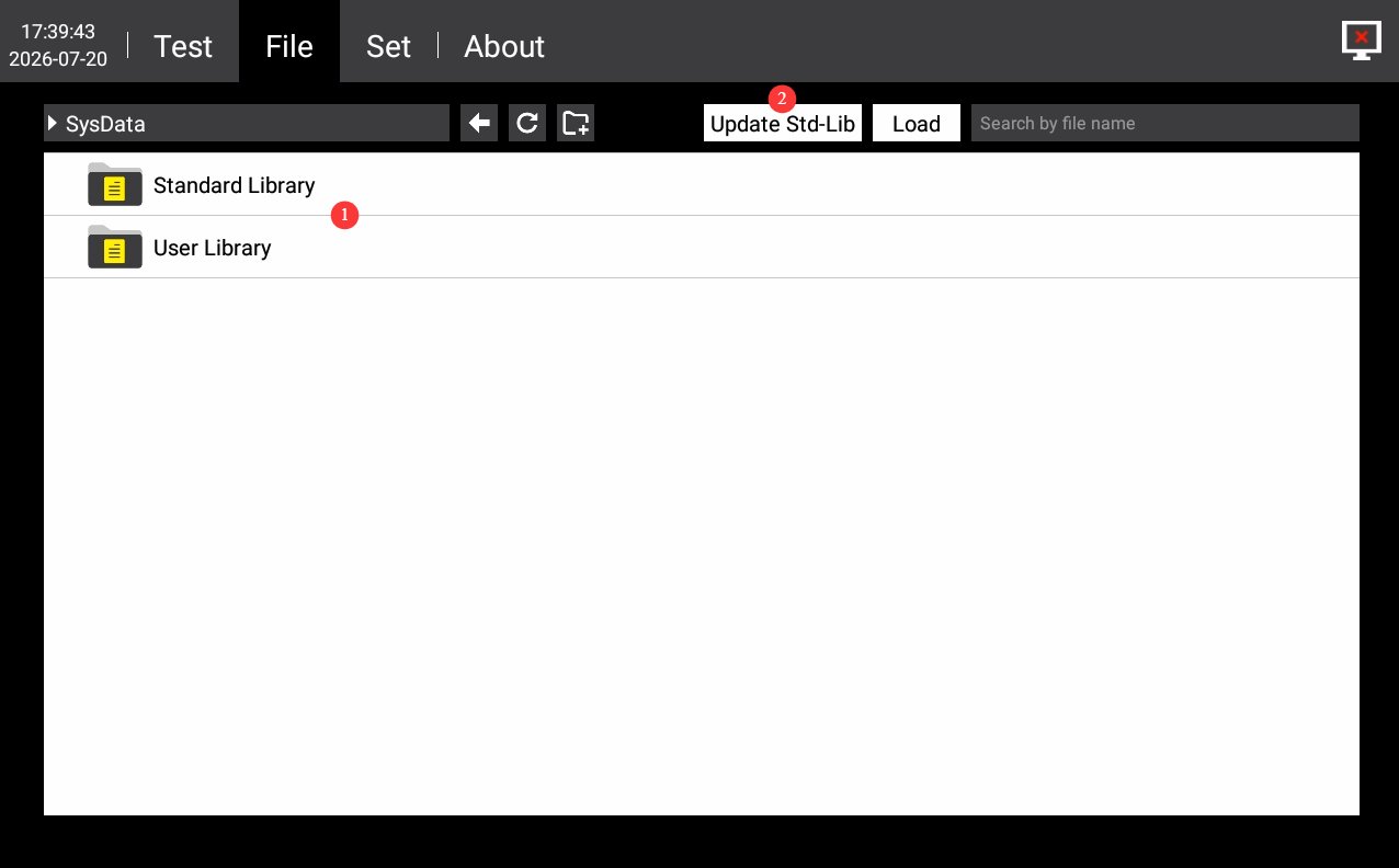
انظر الأشكال من 4 إلى 9.
| رقم الهاتف | ملاحظات |
|---|---|
| ① | Test Plan Standard Library Management. You can manage the custom test parameters you have saved; do not modify or delete the test parameters built into the device. |
| ② | If you have other standard tests but do not wish to create custom tests, please contact us and send us the details of the relevant standards. We will guide you through the process of updating the database file with those standards directly using a USB drive. |
4.3 واجهة الإعدادات
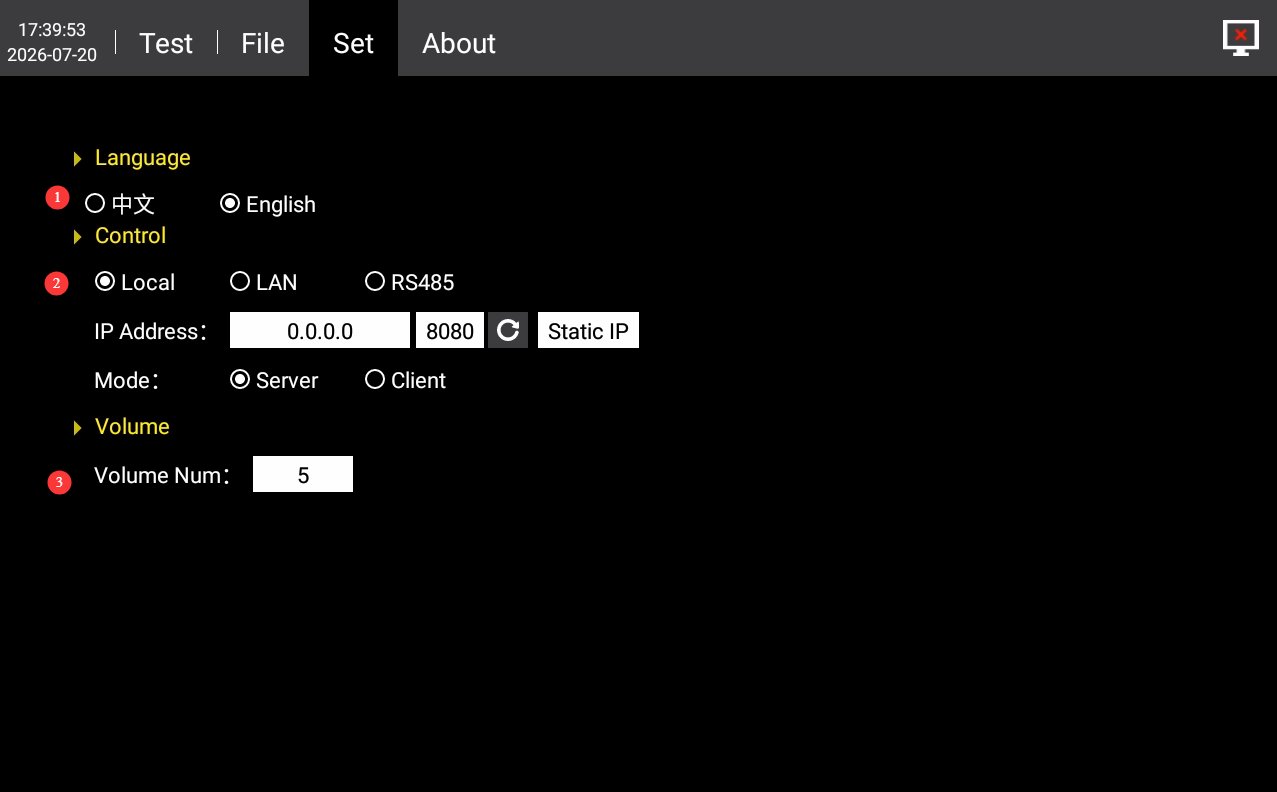
انظر الشكل 4-10.
| رقم الهاتف | ملاحظات |
|---|---|
| ① | التبديل بين اللغتين الصينية والإنجليزية |
| ② | Communication settings are set to “LOCAL” by default. If you need to use host computer software, you can switch to the RS485 or LAN port. Please contact us. |
| ③ | إعدادات حجم |
4.4 About the Interface
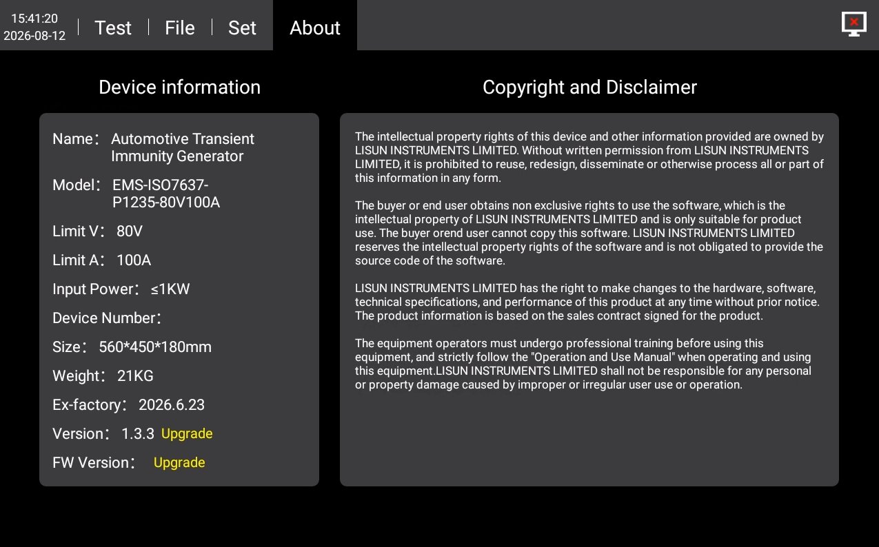
For device information, firmware version, and copyright notice, see Figure 4-11.
5. Procedures for Automotive Electronic Transient Immunity Testing
5.1 Define the Purpose of the Test
| الموجي | غرض التجربة |
|---|---|
| النبض 1 | Verification of the immunity of in-vehicle electronic devices to reverse voltage surges caused by the de-energization of inductive loads |
| نبض 2أ | Verify the device’s immunity to forward voltage spikes caused by stray inductance in the power supply harness |
| نبض 3أ/3ب | Verification of the device’s immunity to high-speed, periodic, narrow pulse trains generated by arcing in mechanical switches |
| نبض 5أ/5ب | Simulate generator load shedding conditions to verify the equipment’s ability to withstand high-energy voltage spikes |
5.2 إجراءات التشغيل العامة
5.2.1 الأسلاك
Ensure that both the equipment and the DUT are powered off; use a test cable to connect the DUT output port on the equipment to the power input port of the device under test (DUT); Use a cable to connect an external power supply (LIS-APS or other regulated DC power supply) to the DUT input power supply connector on the back of the EMS-ISO7637; if external auxiliary equipment is required, complete the wiring as specified.
5.2.2 إعدادات المعلمات
Set the test parameters as described in Section 4.1.
5.2.3 Test Execution Steps
Turn on the external power supply and check the DUT output; turn on the DUT power switch on the back of the EMS-ISO7637; switch to the corresponding waveform test interface, tap the DUT button on the touchscreen to verify that the DUT is operating normally; tap the RUN button to start the test; Observe the DUT’s operating status and record any observations; wait for the test to complete—in case of an emergency, press the Stop button to halt the test immediately.
5.3 تقييم النتائج
Grade A: Functionality is normal during and after testing, with no abnormalities; Grade B: Functionality is temporarily degraded or interrupted during testing but automatically recovers after testing; Grade C: Functionality fails during testing and requires manual intervention to recover; Grade D: The equipment is permanently damaged after testing and cannot be restored.
Standard requirements of major automakers: In-vehicle safety components must meet Grade A standards; for in-vehicle electrical systems and infotainment systems, Grade B may be accepted by mutual agreement, while Grade D is uniformly deemed non-compliant.
5.4 Procedures at the End of the Test
Ensure that both the equipment and the DUT are powered off; wait until the high-voltage capacitors have fully discharged (it is recommended to wait at least 5 minutes); first disconnect the DUT-side connections, then disconnect the equipment-side connections; disconnect the grounding wire and any connections to auxiliary equipment.
6. الصيانة اليومية للمعدات والعناية بها
6.1 التنظيف اليومي
6.1.1 Cleaning Schedule and Procedures
بعد كل استخدام: Clean the touchscreen surface and remove dust from the device panel;
أسبوعيا: Clean the equipment housing and the filters in the vents;
شهري: Clean dust from inside the equipment (to be performed by a professional).
تعليمات التنظيف
Wipe the exterior with a clean, soft, lint-free cloth; use a specialized screen cleaner for the touchscreen; clean the vents with a soft-bristled brush and a vacuum cleaner if necessary; do not use corrosive solvents such as acetone.
6.2 التفتيش الدوري
Check the power cord for damage or wear; check that the ground connection is secure; check that the fan is operating normally; check that the buttons and touchscreen are responsive; check the terminals for oxidation or looseness.
6.3 التخزين والمناولة
6.3.1 متطلبات التخزين طويل الأجل
Storage Conditions: Temperature: -10°C to +50°C; Humidity: ≤85%. Clean the equipment and apply dust protection before storage. Power on the equipment once every 3 months, running it for at least 30 minutes each time. Avoid stacking or applying heavy pressure to prevent the panel from warping.
6.3.2 Precautions for Handling
Unplug all external cables before moving the equipment; use the original packaging and ensure it is properly cushioned and protected; keep the equipment upright during transport and avoid severe vibrations; when lifting, grip the bottom and sides of the equipment; do not lift by the panel.
6.4 متطلبات فترة المعايرة
لضمان دقة القياس وموثوقية تشغيل الجهاز، يُوصى بإرساله دوريًا إلى مختبر قياسات معتمد تابع لجهة خارجية لإجراء المعايرة. يُوصى بإجراء المعايرة كل 12 شهرًا. ويمكن للمستخدمين تحديد فترة المعايرة المناسبة بناءً على وتيرة الاستخدام والظروف البيئية ومتطلبات نظام الجودة.
7. استكشاف الأخطاء وإصلاحها وحل المشكلات الشائعة
| أعراض الخلل | الأسباب المحتملة | العملية |
|---|---|---|
| الجهاز لا يعمل | The input power supply main power switch on the back is not turned on, or the fuse has blown. | Turn on the input power supply switch located at the power cord socket on the back of the device; check the fuse, and if it has blown, replace it with a fuse of the same specification. |
| Touchscreen Malfunction After Power-On | System freeze, loose ribbon cable | If the problem persists after restarting, disconnect the power, remove the device’s casing, and check whether the touchscreen ribbon cable is loose. |
| No pulse output after clicking “RUN” | The DUT did not start up properly | Verify that all connections are secure. Click “DUT” to ensure the DUT is in normal operating condition, then click “RUN” to start the test. |
| Test Stopped Automatically Midway | Over-temperature protection triggered, overcurrent/overvoltage protection triggered, external power supply interruption | Check whether the equipment’s ventilation is obstructed or the ambient temperature is too high; check the DUT for short circuits or overloads; check whether the external power supply has stopped outputting power. |
| USB Drive Not Recognized | USB drive format is incompatible or has too much storage capacity | Use a FAT32-formatted USB drive with a capacity of no more than 32 GB; if that doesn’t work, try a different USB drive. |